Reference Information
Reference Information
Following is reference information for console and auxiliary port pinouts, replacing DRAM SIMMs, configuring the software configuration register, recovering a lost password, and using the
Console Port Signals
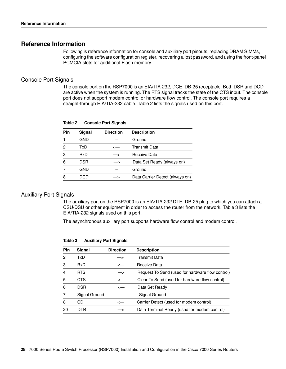
The console port on the RSP7000 is an
Table 2 Console Port Signals
Pin | Signal | Direction | Description |
1 | GND | – | Ground |
|
|
|
|
2 | TxD | <— | Transmit Data |
|
|
|
|
3 | RxD | Receive Data | |
|
|
|
|
6 | DSR | Data Set Ready (always on) | |
|
|
|
|
7 | GND | – | Ground |
|
|
|
|
8 | DCD | Data Carrier Detect (always on) | |
|
|
|
|
Auxiliary Port Signals
The auxiliary port on the RSP7000 is an
The asynchronous auxiliary port supports hardware flow control and modem control.
Table 3 Auxiliary Port Signals
Pin | Signal | Direction | Description |
2 | TxD | Transmit Data | |
|
|
|
|
3 | RxD | <— | Receive Data |
|
|
|
|
4 | RTS | Request To Send (used for hardware flow control) | |
|
|
|
|
5 | CTS | <— | Clear To Send (used for hardware flow control) |
|
|
|
|
6 | DSR | <— | Data Set Ready |
|
|
|
|
7 | Signal Ground | – | Signal Ground |
|
|
|
|
8 | CD | <— | Carrier Detect (used for modem control) |
|
|
|
|
20 | DTR | Data Terminal Ready (used for modem control) | |
|
|
|
|
287000 Series Route Switch Processor (RSP7000) Installation and Configuration in the Cisco 7000 Series Routers
