Reference Information
Before proceeding, ensure that you have the proper tools and
Note Depending on your router configuration, Cisco IOS Release 11.1(1) might require more than 16 MB of DRAM for your RSP7000. Upgrade your system DRAM based on your current configuration and this potential requirement.
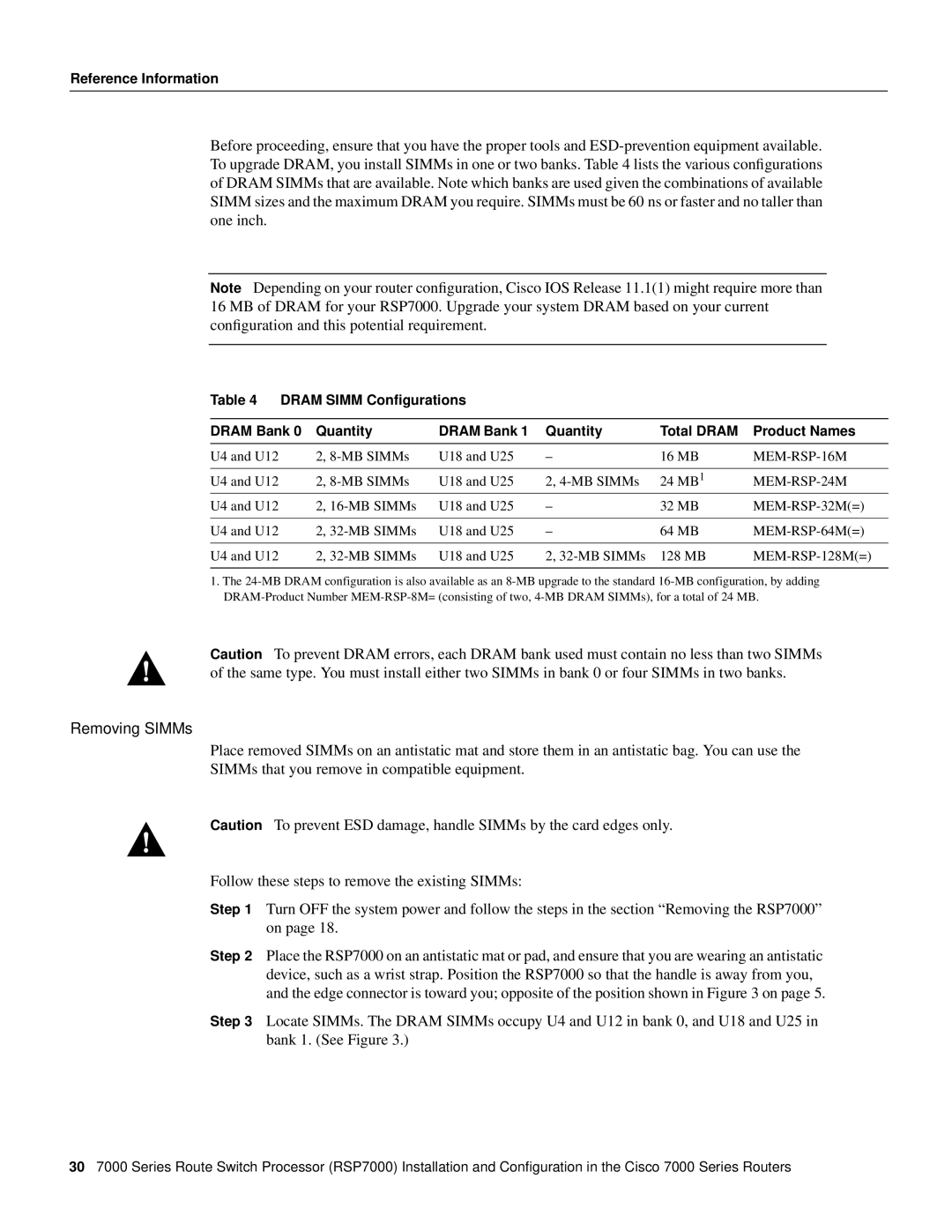
Table 4 DRAM SIMM Configurations
DRAM Bank 0 | Quantity | DRAM Bank 1 | Quantity | Total DRAM | Product Names |
U4 and U12 | 2, | U18 and U25 | – | 16 MB | |
|
|
|
|
|
|
U4 and U12 | 2, | U18 and U25 | 2, | 24 MB1 |
|
U4 and U12 | 2, | U18 and U25 | – | 32 MB | |
|
|
|
|
|
|
U4 and U12 | 2, | U18 and U25 | – | 64 MB | |
|
|
|
|
|
|
U4 and U12 | 2, | U18 and U25 | 2, | 128 MB |
|
|
|
|
|
|
|
1.The
Caution To prevent DRAM errors, each DRAM bank used must contain no less than two SIMMs of the same type. You must install either two SIMMs in bank 0 or four SIMMs in two banks.
Removing SIMMs
Place removed SIMMs on an antistatic mat and store them in an antistatic bag. You can use the
SIMMs that you remove in compatible equipment.
Caution To prevent ESD damage, handle SIMMs by the card edges only.
Follow these steps to remove the existing SIMMs:
Step 1 Turn OFF the system power and follow the steps in the section “Removing the RSP7000” on page 18.
Step 2 Place the RSP7000 on an antistatic mat or pad, and ensure that you are wearing an antistatic device, such as a wrist strap. Position the RSP7000 so that the handle is away from you, and the edge connector is toward you; opposite of the position shown in Figure 3 on page 5.
Step 3 Locate SIMMs. The DRAM SIMMs occupy U4 and U12 in bank 0, and U18 and U25 in bank 1. (See Figure 3.)
307000 Series Route Switch Processor (RSP7000) Installation and Configuration in the Cisco 7000 Series Routers