Installation Procedures
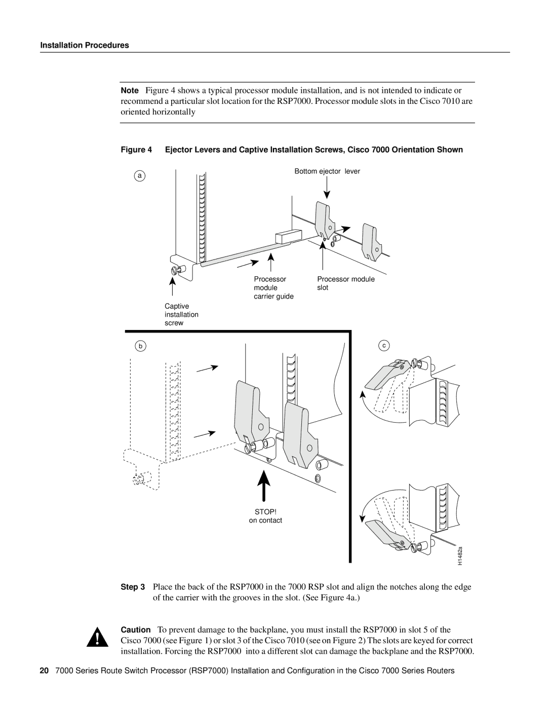
Note Figure 4 shows a typical processor module installation, and is not intended to indicate or recommend a particular slot location for the RSP7000. Processor module slots in the Cisco 7010 are oriented horizontally
Figure 4 Ejector Levers and Captive Installation Screws, Cisco 7000 Orientation Shown
a
Bottom ejector lever
Processor | Processor module |
module | slot |
carrier guide |
|
Captive |
|
installation |
|
screw |
|
b | c |
STOP! |
|
on contact |
|
| H1482a |
Step 3 Place the back of the RSP7000 in the 7000 RSP slot and align the notches along the edge of the carrier with the grooves in the slot. (See Figure 4a.)
Caution To prevent damage to the backplane, you must install the RSP7000 in slot 5 of the Cisco 7000 (see Figure 1) or slot 3 of the Cisco 7010 (see on Figure 2) The slots are keyed for correct installation. Forcing the RSP7000 into a different slot can damage the backplane and the RSP7000.
207000 Series Route Switch Processor (RSP7000) Installation and Configuration in the Cisco 7000 Series Routers
