Chapter 5 | Configuration Using the |
Default Gateway The IP address (default 0.0.0.0) of the gateway router between the Switch and management stations on other network segments. This setting can be configured from the Setup tab’s Network Settings screen.
NOTE: The Default Gateway cannot be configured if the system IP address is set to 192.168.1.254. (The system IP Address is set using Setup > Network Settings.)
Address Mode Specifies whether the Switch’s IP address is Static or dynamically assigned using DHCP (Dynamic Host Configuration Protocol). This setting can be configured from the Setup tab’s Network Settings screen. The default setting is Static.
Base MAC Address Displays the Switch’s MAC address.
Jumbo Frame This setting enables or disables Jumbo frames on the Switch. A maximum packet size of 9 KB is supported. Jumbo frames allow data to be transmitted using fewer frames, providing lower overhead, quicker processing time, and fewer interruptions. Select either Enable or Disable (default).
NOTE: The Jumbo Frame feature functions only on the Gigabit ports
Switch Mode After Reset This setting specifies the system mode following a system reset. Select either Standalone or Stackable (default).
System Information
Model Name Displays the model name of the Switch. Hardware Version Displays the current hardware version. Boot Version Displays the current boot version. Firmware Version Displays the current software version
System Location Displays the location of the system if it has been defined. This setting can be configured from the Setup tab’s Network Settings screen.
System Contact The name of the administrator appears here, if one has been defined.This setting can be configured from the Setup tab’s Network Settings screen.
System Up Time Displays the length of time that has elapsed since the Switch was last reset.
Current Time Displays the current time. This setting can be configured from the Setup tab’s Time screen.
Click Save Settings to save your changes. Click Cancel Changes to cancel your changes.
Setup > Zoom
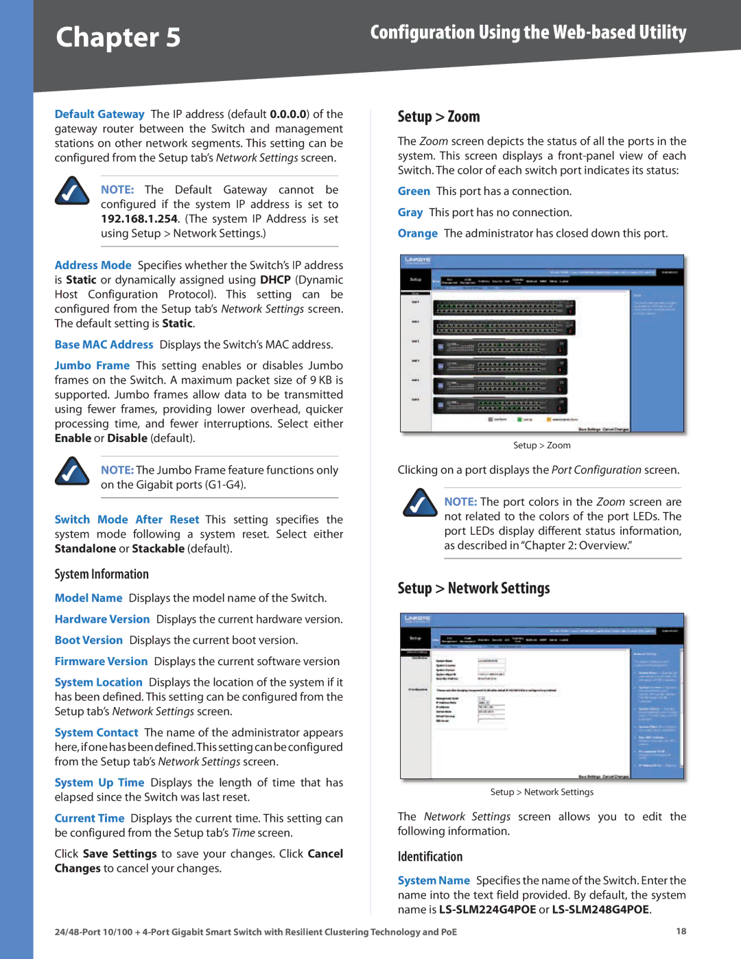
The Zoom screen depicts the status of all the ports in the system. This screen displays a
Green This port has a connection. Gray This port has no connection.
Orange The administrator has closed down this port.
Setup > Zoom
Clicking on a port displays the Port Configuration screen.
NOTE: The port colors in the Zoom screen are not related to the colors of the port LEDs. The port LEDs display different status information, as described in “Chapter 2: Overview.”
Setup > Network Settings
Setup > Network Settings
The Network Settings screen allows you to edit the following information.
Identification
System Name Specifies the name of the Switch. Enter the name into the text field provided. By default, the system name is
18 |
