Chapter 5 | Configuration Using the |
Spanning Tree
Spanning Tree Protocol (STP) provides tree topography for any arrangement of bridges. STP also provides one path between end stations on a network, eliminating loops.
Loops occur when alternate routes exist between hosts. Loops in an extended network can cause bridges to forward traffic indefinitely, resulting in increased traffic and reducing network efficiency.
The Switch supports the Classic STP version of STP, which provides a single path between end stations, avoiding and eliminating loops.
Spanning Tree > STP Status
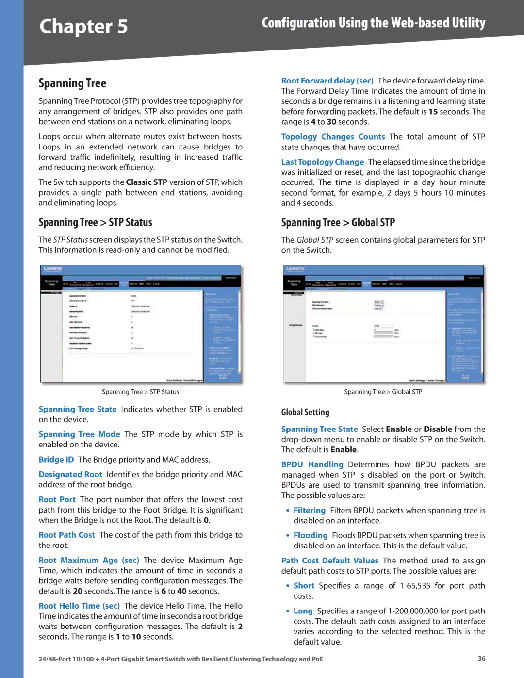
The STP Status screen displays the STP status on the Switch. This information is
Spanning Tree > STP Status
Spanning Tree State Indicates whether STP is enabled on the device.
Spanning Tree Mode The STP mode by which STP is enabled on the device.
Bridge ID The Bridge priority and MAC address.
Designated Root Identifies the bridge priority and MAC address of the root bridge.
Root Port The port number that offers the lowest cost path from this bridge to the Root Bridge. It is significant when the Bridge is not the Root. The default is 0.
Root Path Cost The cost of the path from this bridge to the root.
Root Maximum Age (sec) The device Maximum Age Time, which indicates the amount of time in seconds a bridge waits before sending configuration messages. The default is 20 seconds. The range is 6 to 40 seconds.
Root Hello Time (sec) The device Hello Time. The Hello Time indicates the amount of time in seconds a root bridge waits between configuration messages. The default is 2 seconds. The range is 1 to 10 seconds.
Root Forward delay (sec) The device forward delay time. The Forward Delay Time indicates the amount of time in seconds a bridge remains in a listening and learning state before forwarding packets. The default is 15 seconds. The range is 4 to 30 seconds.
Topology Changes Counts The total amount of STP state changes that have occurred.
LastTopology Change The elapsed time since the bridge was initialized or reset, and the last topographic change occurred. The time is displayed in a day hour minute second format, for example, 2 days 5 hours 10 minutes and 4 seconds.
Spanning Tree > Global STP
The Global STP screen contains global parameters for STP on the Switch.
Spanning Tree > Global STP
Global Setting
Spanning Tree State Select Enable or Disable from the
BPDU Handling Determines how BPDU packets are managed when STP is disabled on the port or Switch. BPDUs are used to transmit spanning tree information. The possible values are:
•Filtering Filters BPDU packets when spanning tree is disabled on an interface.
•Flooding Floods BPDU packets when spanning tree is disabled on an interface. This is the default value.
Path Cost Default Values The method used to assign default path costs to STP ports. The possible values are:
•Short Specifies a range of
•Long Specifies a range of
36 |