Installing Adapters in the
Installing an Inline Network Adapter
The
Note The PCI riser card is located at J73 on the system board.
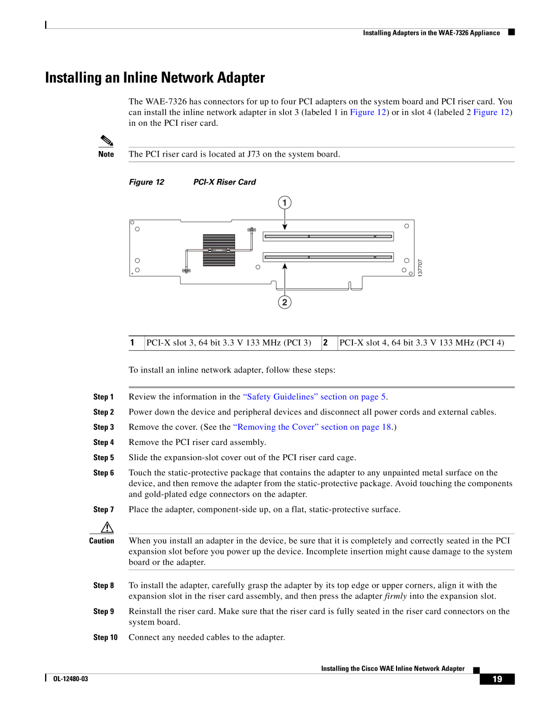
Figure 12 |
|
1
137707
2
1
2
To install an inline network adapter, follow these steps:
Step 1 Review the information in the “Safety Guidelines” section on page 5.
Step 2 Power down the device and peripheral devices and disconnect all power cords and external cables. Step 3 Remove the cover. (See the “Removing the Cover” section on page 18.)
Step 4 Remove the PCI riser card assembly.
Step 5 Slide the
Step 6 Touch the
Step 7 Place the adapter,
Caution When you install an adapter in the device, be sure that it is completely and correctly seated in the PCI expansion slot before you power up the device. Incomplete insertion might cause damage to the system board or the adapter.
Step 8 To install the adapter, carefully grasp the adapter by its top edge or upper corners, align it with the expansion slot in the riser card assembly, and then press the adapter firmly into the expansion slot.
Step 9 Reinstall the riser card. Make sure that the riser card is fully seated in the riser card connectors on the system board.
Step 10 Connect any needed cables to the adapter.
Installing the Cisco WAE Inline Network Adapter
| 19 |
| |
|
|