Installing Adapters in the
Caution For proper cooling and airflow, replace the cover before turning on the device. Operating the device for extended periods (over 30 minutes) with the cover removed might damage device components.
Installing an Inline Network Adapter
The
To install an inline network adapter in the
Step 1 Review the information in the “Safety Guidelines” section on page 5.
Step 2 Power down the device and peripheral devices and disconnect all power cords and external cables. Step 3 Remove the cover. (See the “Removing the Cover” section on page 22.)
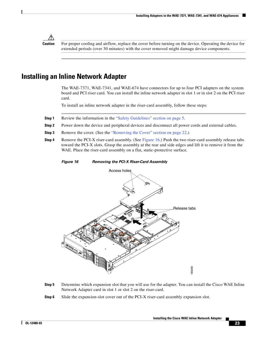
Step 4 Remove the
Figure 16 Removing the PCI-X Riser-Card Assembly
Access holes
Release tabs
185090
Step 5 Determine which expansion slot that you will use for the adapter. You can install the Cisco WAE Inline Network Adapter card in slot 1 or slot 2 on the
Step 6 Slide the
Installing the Cisco WAE Inline Network Adapter
| 23 |
| |
|
|
