Linksys X2000/X3000 | Product Overview |
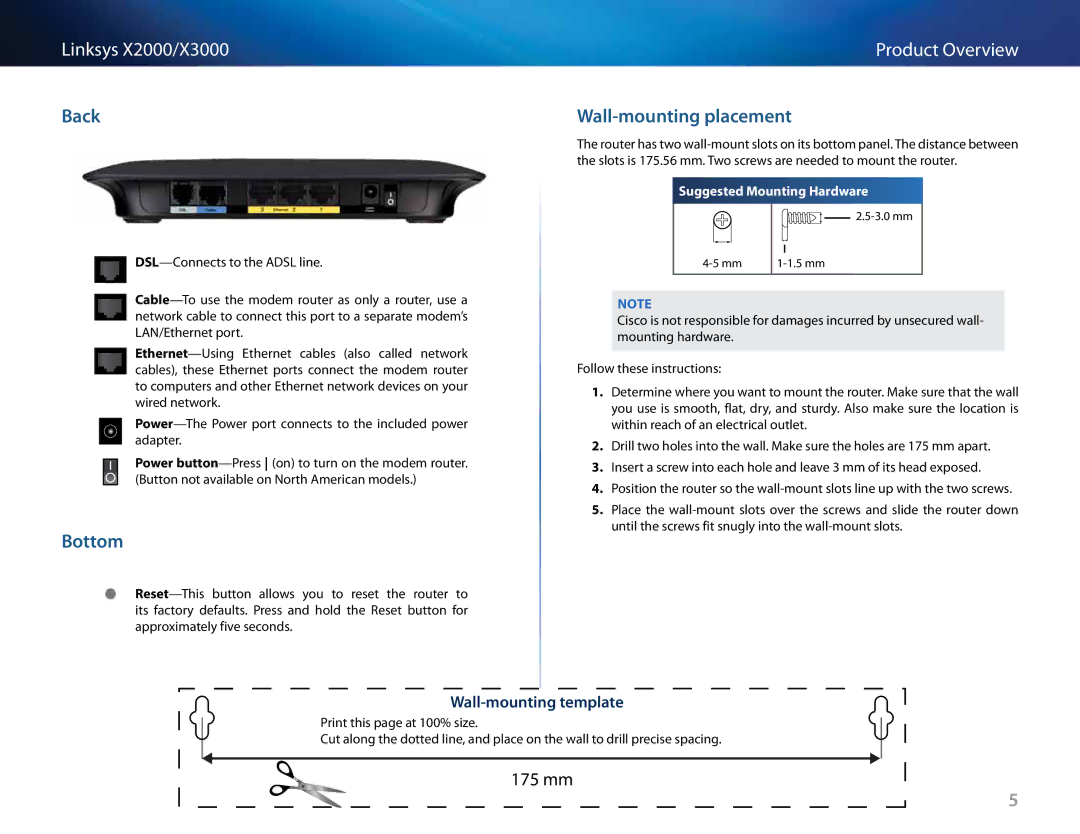
Back
Power
Bottom
Wall-mounting placement
The router has two
Suggested Mounting Hardware
![]()
![]()
![]()
![]()
![]()
![]()
![]()
Note
Cisco is not responsible for damages incurred by unsecured wall- mounting hardware..
Follow these instructions:
1.Determine where you want to mount the router.. Make sure that the wall you use is smooth, flat, dry, and sturdy.. Also make sure the location is within reach of an electrical outlet..
2.Drill two holes into the wall.. Make sure the holes are 175 mm apart..
3.Insert a screw into each hole and leave 3 mm of its head exposed..
4.Position the router so the
5.Place the
Wall-mounting template
Print this page at 100% size..
Cut along the dotted line, and place on the wall to drill precise spacing..
175 mm
5