Manuals
/
Citizen
/
Computer Equipment
/
Printer
Citizen
CBM-270
user manual
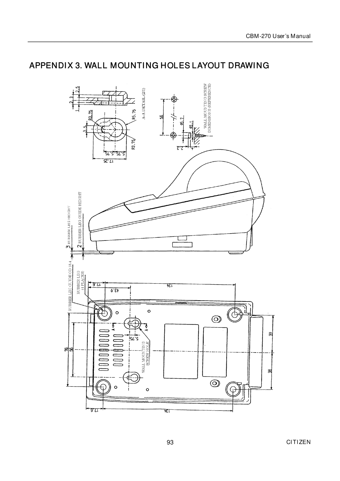
Appendix 3. Wall Mounting Holes Layout Drawing
Models:
CBM-270
1
93
114
114
Download
114 pages
19.21 Kb
90
91
92
93
94
95
96
97
Specification
Electrical Characteristics
Install
Timing Chart
Input and Output Signals
Error Details
Connecting AC Adapter
Maintenance
Connectors Pin Configuration
Command List
Page 93
Image 93
CBM-270
User’s Manual
APPENDIX 3. WALL MOUNTING HOLES LAYOUT DRAWING
93
CITIZEN
Page 92
Page 94
Page 93
Image 93
Page 92
Page 94
Contents
Citizen
EMC
LVD
Important Safety Instructions
Lärmemission kleiner 70dBA
Wichtige Sicherheitsanweisungen
Sicherheitshinweis
Citizen
Safety Precautions Be Sure to Observe
Citizen
Precautions for Installation
Precautions for Handling
Daily Maintenance
Contents
Parallel Interface
Maintenance and Service Print Control Functions
Appendix
German
Appendix Wall Mounting Holes Layout Drawing
DIP-SCHALTEREINSTELLUNG
Features
Outline
Unpacking
Model Classifications
Basic Specifications
UL, C-UL
Basic Specifications
Recommended Paper
Paper Specifications
Head and Paper Cutter Layout
Printing Position
Outer Appearance and Component Parts
Citizen
Operation
Connecting AC Adapter
Connecting Interface Cable
Inserting the Paper
How to Remove Remaining Paper Roll
Eliminating the Paper Jam
When Thermal Paper is Used
Feed Switch Function
When Label Paper is Used
When the Macro is Executed
OFF
Paper Near End Function
Self-Print Function
Auto-Loading Function
Error Details
Operation Panel and Display of Error
OFF
Busy
Mitsubishi Paper Mills
12 Red/Black Print Precautions for Use
Location of DIP Switch
DIP Switch Setting
DIP Switch Function
DS2 For Serial Interface Only
USA
Jumper Wire Function
Specifications
Connectors Pin Configuration
Parallel Interface
Input and Output Signals
Input and Output Signals
Electrical Characteristics
Timing Chart
Data Receiving Control
Buffering
RXD
Serial Interface
DTR
TXD
Input and Output Signals
Error Detection
Data Configuration
Input RXD, DSR Printer Side Host Side
Power Connector
Maintenance and Service
Print Control Functions
10.1 Command List
0AH
0DH ESC
1DH 3AH
1DH 2AH
DC2
DC3
Command Details
Descriptions of Each Item
Xxxx
ESC D
Command Details
Citizen
ESC SP
Citizen
ESC E, ESC
ESC
ESC %
A p s´a m-n+1
ESC * m N1 n2 d
Print Results Dots single density Dots double density
ESC n
ESC =
ESC D n k NUL
ESC @
ESC G
ESC E
ESC !, ESC G
ESC E
ESC J
ESC R
ESC
ESC a
ESC c
ESC c Parallel Interface Only
ESC d
ESC t
ESC Serial Interface Only
Lprint Aaaaa CHR$ &HA Lprint Bbbbb CHR$ &HA
ESC ¥
ESC $
ESC $
ESC ¥
GS k n
NUL
UPC-A UPC-E JAN13 EAN JAN 8 EAN Code ITF Codabar NW-7
JAN-8EAN
CODE39
CODE128
Code Btestcode A123
Test
Description of Bar Codes
GS h n
GS w
GS H
GS H
GS f n
See Also GS /, ESC N1´8 dots N2´8 dots Sample Program
GS * n1 N2 d n1 ´ n2 ´
GS / m
Lprint CHR$ END
GS n1 n2 n3
DC3 n
DC2 a
Only When Label Printer is Selected
GS FF
GS FF, GS
GS C0
Lprint CHR$ 0 CHR$
GS C N1 N2 N3 N4 N5
GS C2
GS c
GS a m Only When Label Printer is Selected
International Domestic
Character Codes Table
International Character Codes Table
Appendix 1. Block Diagram
Appendix 2. Outline Drawing
Appendix 3. Wall Mounting Holes Layout Drawing
German
Vorsicht
ZU Beachtende Sicherheitsmassregeln
Warnung
Vorsichtsmassregeln FÜR DIE Aufstellung
Vorsichtsmassregeln FÜR DIE Handhabung
Vorsicht
Tägliche Wartung
Anschließen des Netzteils
Betrieb
Anschließen des Schnittstellenkabels
Einsetzen des Papiers
Entnehmen der eingesetzten Papierrolle
Beseitigen von Papierstau
Papierende-Funktion
FEED-Schalterfunktion
Bei Verwendung von Thermalpapier
Bei Verwendung von Etikettenpapier
Papiermangel-Funktion
Selbstdruckfunktion
Autoladefunktion
Bedienfeld und Fehleranzeigen
Fehler-Einzelheiten
12 Rot/Schwarz-Druck Vorsichtsmaßregeln
Lage der DIP-Schalter
DIP-SCHALTEREINSTELLUNG
DIP-Schalterfunktion
DS1
Jumperdraht-Funktion
Wartung UND Dienst
Top
Page
Image
Contents