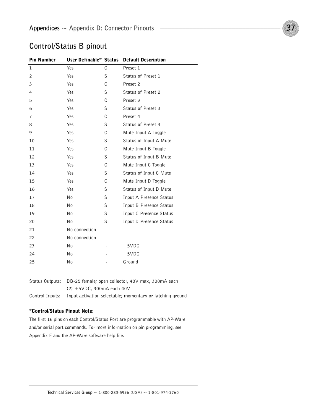
AP800 specifications
ClearOne has established itself as a leader in the audio and video communication technology space, and the ClearOne COMM AP800 is a prime example of the company's commitment to providing high-quality communication solutions. The AP800 is an advanced audio processing unit specifically designed for professional audio environments, including conference rooms, auditoriums, and other large venues that require exceptional audio clarity and performance.One of the standout features of the ClearOne COMM AP800 is its robust digital signal processing capabilities. It is equipped with powerful, sophisticated algorithms that enhance audio quality by minimizing background noise and echo, ensuring crystal-clear communication even in challenging acoustic environments. This makes the AP800 ideal for videoconferencing, teleconferencing, and live events where audio fidelity is paramount.
The AP800 features multiple microphone inputs, allowing users to connect a variety of microphone types, including boundary microphones and handheld units. This versatility enables configuration for different setups, ensuring that audio coverage is optimal for all participants regardless of their location within the space.
Another impressive characteristic of the ClearOne COMM AP800 is its user-friendly interface. The unit comes with a graphical interface that simplifies configuration and control. Users can easily manage audio settings, adjust levels, and monitor system performance in real time. This intuitive design streamlines setup and operation, making it accessible for users at all technical skill levels.
The AP800 also supports VoIP and SIP technologies, making it an ideal solution for businesses looking to integrate their audio systems with modern communication networks. This feature enhances interoperability with various communication platforms and devices, ensuring seamless connectivity for users.
For added flexibility, the ClearOne COMM AP800 can be integrated into larger audio systems. It can work harmoniously with other ClearOne products and third-party equipment, leveraging its modular design to create a comprehensive communication environment tailored to specific needs.
In summary, the ClearOne COMM AP800 represents a significant advancement in audio processing technology, offering state-of-the-art features for high-performance audio applications. Its powerful DSP capabilities, versatile microphone support, user-friendly interface, and seamless integration capabilities make it a must-have for any organization seeking to elevate their audio communication experience. With the AP800, ClearOne continues to push the boundaries of what's possible in professional audio technology.

