Maintenance and Service Guide
Page
Contents
Removal and Replacement Procedures
Removal and Replacement Preliminaries
Illustrated Parts Catalog
Screw Listing Index
Product Description
HP Compaq Notebook nc4000 Model Naming Conventions
Models
Key Description Options
HP Compaq Notebook nc4000 Models
DG993A UUF
DG245A UUF
Features
Product Description
Clearing a Password
Power Management
Front and Right Side Components
External Components
Component Function
Front and Right Side Components
Rear Panel and Left Side Components
Item Component Function
Caps lock key
Keyboard Components
Num lock light
Top Components
Top Components
Bottom Components
Bottom Components
Design Overview
Computer Setup and Diagnostics Utilities
Troubleshooting
Using Computer Setup
Select To Do This
File Menu
Security Menu
Selecting from the Security Menu
Advanced Menu
Selecting from the Advanced Menu
Advanced Menu
Obtaining, Saving, or Printing Configuration Information
Using Diagnostics for Windows
Obtaining, Saving, or Printing Diagnostic Test Information
Troubleshooting
Troubleshooting Flowcharts Overview
Troubleshooting Flowcharts
Flowchart Description
Is there power? Go to Section No Power
Flowchart 2.1-Initial Troubleshooting
Go to Section No Power Part Power up On AC Power? Reset
Flowchart 2.2-No Power, Part
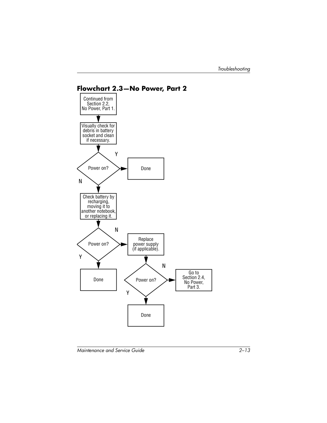
Flowchart 2.3-No Power, Part
Internal
Flowchart 2.4-No Power, Part
Flowchart 2.5-No Power, Part
Flowchart 2.6-No Video, Part
From Section No Video, Part Remove
Flowchart 2.7-No Video, Part
Reseat power Cord in docking Station Power outlet
Flowchart 2.8-Nonfunctioning Docking Station if applicable
Flowchart 2.9-No Operating System OS Loading
Flowchart 2.10-No OS Loading, Hard Drive, Part
Flowchart 2.11-No OS Loading, Hard Drive, Part
Flowchart 2.12-No OS Loading, Hard Drive, Part
Flowchart 2.13-No OS Loading, Diskette Drive
Flowchart 2.14-No OS Loading, CD- or DVD-ROM Drive
Go to Section No Audio, Part Undock
Flowchart 2.15-No Audio, Part
Flowchart 2.16-No Audio, Part
Cmos
Flowchart 2.17-Nonfunctioning Device
Flowchart 2.18-Nonfunctioning Keyboard
Flowchart 2.19-Nonfunctioning Pointing Device
Flowchart 2.20-No Network/Modem Connection
Serial Number Location
Illustrated Parts Catalog
Illustrated Parts Catalog
Spare Part
Spare Parts Notebook Major Components
Description Number
Illustrated Parts Catalog
TouchPad with cable
Illustrated Parts Catalog
Processors
Item Description Number
Miscellaneous Plastics Kit Components
Item Description
Miscellaneous Plastics Kit Components Spare Part Number
Port Replicators and Mass Storage Devices
Port Replicators and Mass Storage Devices
Spare Parts Miscellaneous not illustrated
Miscellaneous
Description Spare Part Number
Travel battery carrier 325527-001
Tools Required
Removal and Replacement Preliminaries
Plastic Parts
Service Considerations
Preventing Damage to Removable Drives
Preventing Electrostatic Damage
Packaging and Transporting Precautions
Workstation Precautions
Grounding Equipment and Methods
Static-Shielding Materials
Typical Electrostatic Voltage Levels
Event 10% 40% 55%
Material Use Voltage Protection Level
Removal and Replacement Procedures
Disassembly Sequence Chart
Disassembly Sequence Chart
Serial Number
# of Screws
Removal and Replacement Procedures
Battery Pack Spare Part Number Information
Preparing the Notebook for Disassembly
Hard Drive
Removing the Hard Drive Lower Bezel
Removing the Hard Drive from the Hard Drive Frame
Replacing the Notebook Feet
Memory Expansion Boards
Memory Expansion Board
Mini PCI Communications Boards Spare Part Number Information
Mini PCI Communications Board
Removing the Mini PCI Compartment Cover
Removing a Mini PCI Communications Board
LED Switch Cover Spare Part Number Information
LED Switch Cover
Reverse the above procedure to install the LED switch cover
Keyboards Spare Part Number Information
Keyboard
Removing the Keyboard Screw
Releasing the Keyboard
Removing the Keyboard
Removing an Internal Memory Expansion Board
Fan Spare Part Number Information
Fan
Reverse the above procedure to install the fan
Heat Sink Spare Part Number Information
Heat Sink
Removing the Heat Sink Screws
Heat Sink Screw Removal and Installation Sequence
Removing the Heat Sink
Processor Spare Part Number Information
Processor
Reverse the above procedure to install the processor
Display Assembly Spare Part Number Information
Display Assembly
Removing the Hinge Covers
Removing the Antenna Cables
Removal and Replacement Procedures
Top Cover Spare Part Number Information
Top Cover
Turn the notebook top side up with the front facing forward
Disconnecting the Top Cover Cables
Reverse the above procedure to install the top cover
Bluetooth Wireless Device Spare Part Number Information
Bluetooth Wireless Device
TouchPad Spare Part Number Information
TouchPad
Removing the TouchPad Screws
Reverse the above procedure to install the TouchPad
RTC Battery
Speaker/Microphone
Switch Board Spare Part Number Information
Switch Board
System Board Spare Part Number Information
System Board
Removing the System Board Screws
Reverse the above procedure to install the system board
Modem Board Spare Part Number Information
Modem Board
Reverse the above procedure to install the modem board
Specifications
Shock
Inch XGA, TFT Display
60 GB 40 GB 30 GB
Hard Drives
External AC Adapter
Cell, Primary Li ion Battery Pack
Cell, Travel Li ion Battery Pack
Hardware System
System DMA
IRQ
System Interrupts
Address System Function
System I/O Addresses
16F Unused
VGA
Size Memory Address System Function
System Memory Map
RJ-45 Network Interface
Connector Pin Assignments
Table A-3 Universal Serial Bus
Table A-2 RJ-11 Modem
Table A-4 Video
Table A-5 External Monitor
Microphone
Stereo Speaker/Headphone
General Requirements
Conductor Power Cord Set
Country-Specific Requirements
Conductor Power Cord Set Requirements
Applicable Note
Country Accredited Agency Number
BSI
Screw Listing
Head
Table C-1 Phillips PM2.5×3.0 Screw
Color Qty Length Thread Width
Table C-2
Table C-3 Phillips PM2.5×3.5 Screw
Table C-4 Mm Socket M2.0×10.0 Alignment Pin
Silver 10.0 mm Where used
Table C-5
Black Phillips PM2.0×3.0 Screw
Table C-6 Phillips PM2.0×4.0 Screw
Head Color Qty. Length Thread Width
Table C-6 Phillips PM2.0×4.0 Screw
Table C-7
M2.0×4.0 Security Screw
Table C-8 Silver Phillips PM2.0×3.0 Screw
Table C-8 Silver Phillips PM2.0×3.0 Screw
Table C-8 Silver Phillips PM2.0×3.0 Screw
Table C-9
Torx T8 M2.0×8.0 Screw
Table C-9 Torx T8 M2.0×8.0 Screw
Table C-9 Torx T8 M2.0×8.0 Screw
Table C-9 Torx T8 M2.0×8.0 Screw
Table C-10
Spring-Loaded Torx T8 M2.0×10.0 Screw
Table C-11 Torx T8 M2.0×4.0 Screw
Black 12 4.0 mm 2.0 mm 4.5 mm
Table C-11 Torx T8 M2.0×4.0 Screw
Table C-12
Torx T8 M2.0×6.0 Screw
Table C-13 Mm Socket M2.0×9.0 Standoff
Index
Index
Index-3
Index-4
Index-5
Index-6