Compur Statox 4120
Slide switch S1:
| S1 |
| ON |
|
| OFF |
|
|
|
|
|
| |||
| 1 |
| Relay active during alarm A2 |
|
| Relay inactive at alarm A2 |
|
| 2 |
| Relay active during alarm A1 |
|
| Relay inactive at alarm A1 |
|
Toggle switch S3:
S3 | ON | OFF |
1 | Detection mode | - |
2 | Rest Alarm by resetbutton R | auto - reset |
3 | Detection mode | - |
4 | Detection mode | - |
5 | Measured value accepted if logic | - |
| signal is 0V |
|
6 | Detection mode | - |
7 | Detection mode | Modem - and analog signal |
|
| adjustment for service only! |
8 | Detection mode | Delete EPROM for service only! |
Ex works settings
3.4 Switch positions of the sensor head pcb
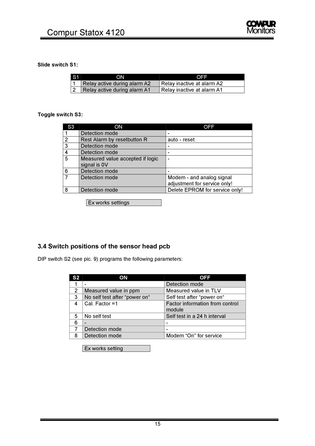
DIP switch S2 (see pic. 9) programs the following parameters:
S2 | ON | OFF |
1 | - | Detection mode |
2 | Measured value in ppm | Measured value in TLV |
3 | No self test after “power on“ | Self test after “power on“ |
4 | Cal. Factor =1 | Factor information from control |
|
| module |
5 | No self test | Self test in a 24 h interval |
6 | - | - |
7 | Detection mode | - |
8 | Detection mode | Modem “On” for service |
Ex works setting
15
