Compur Statox 4120
8. The option analog output inhibition
This option inhibits the analog output if the logic signal of the control module (see pic. 3, terminal 11) is set to 5 V instead of 0 V. This is the case if the system is unable to provide a valid measured value, for instance if:
-Alarm thresholds are adjusted or displayed
-During self test
-During the diagnostic box is connected
-During system start.
As soon as the sensor head provides the next valid data telegram, the analog output is activated again. This option will work with control module equipped with EPROM 02!
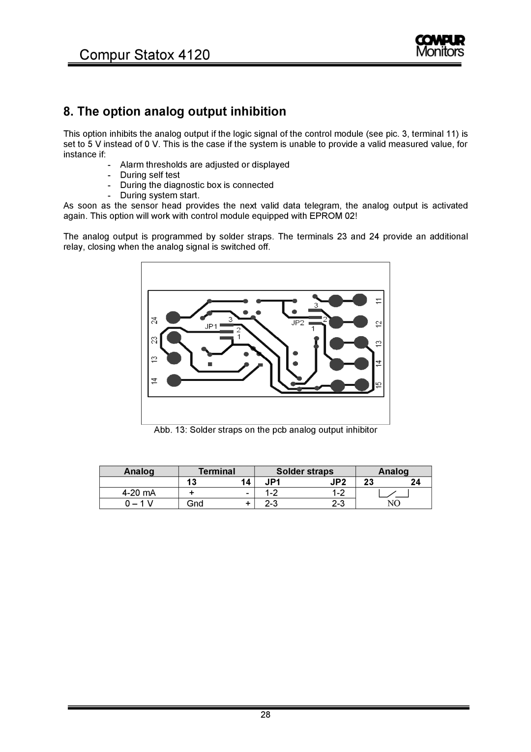
The analog output is programmed by solder straps. The terminals 23 and 24 provide an additional relay, closing when the analog signal is switched off.
Abb. 13: Solder straps on the pcb analog output inhibitor
Analog | Terminal |
| Solder straps |
| Analog | |
| 13 | 14 | JP1 | JP2 | 23 | 24 |
+ | - |
| NO | |||
0 – 1 V | Gnd | + |
| |||
28
