Compur Statox 4120
Construction:
The system consists of a
STATOX 4120 Rack ½ x 19“ for 4 Control modules
STATOX 4120 | Rack 19“ for 9 Control modules | |
STATOX 4120 | Rack 19“ for 9 Control modules / RFI shielded | |
STATOX 4120 | Desk case for | 4 Control modules |
STATOX 4120 | Desk case for | 19“ Rack with 9 Control modules |
Connections:
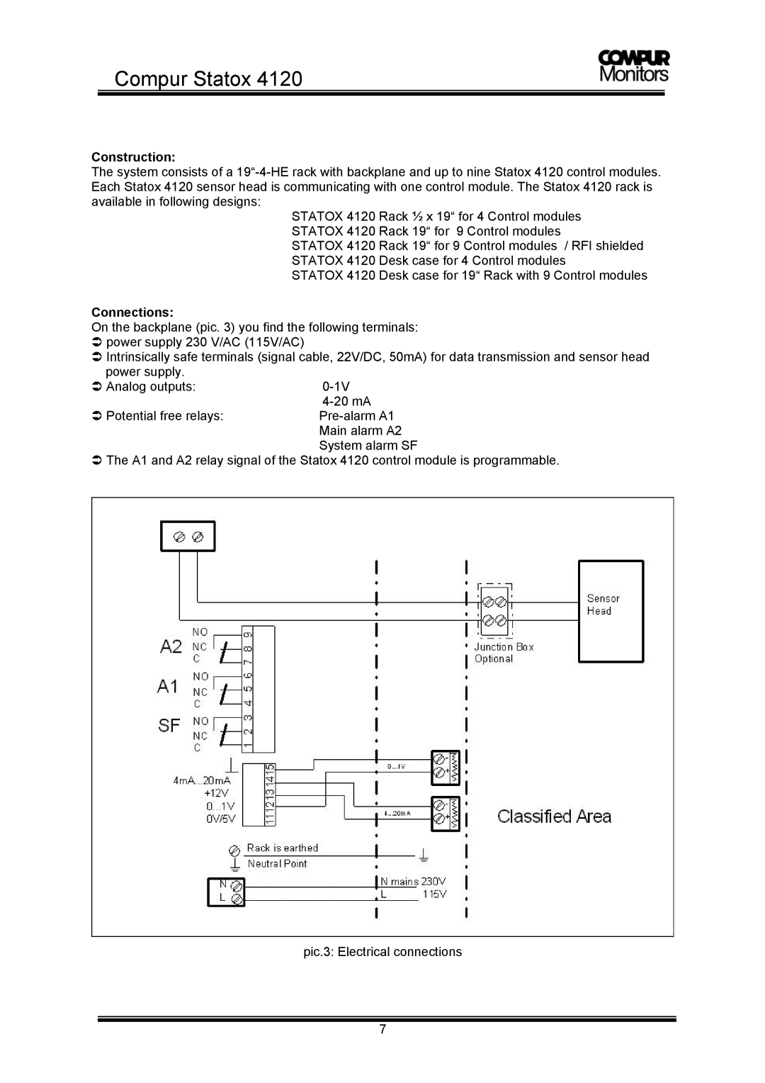
On the backplane (pic. 3) you find the following terminals: power supply 230 V/AC (115V/AC)
Intrinsically safe terminals (signal cable, 22V/DC, 50mA) for data transmission and sensor head power supply.
Analog outputs: | |
| |
Potential free relays: | |
| Main alarm A2 |
| System alarm SF |
The A1 and A2 relay signal of the Statox 4120 control module is programmable.
pic.3: Electrical connections
7
