5.4.8 Front Document Roller Spring Force
Gate travel must be properly adjusted (see 5.4.7) before roller spring force is adjusted
1.Raise the gate by pressing 9 4 7 FUNCT ↑A.
2.Rotate a lower drive gear to manually feed an ½” wide strip of the thinnest paper used (usually a receipt copy) under the rightmost front upper roller segment.
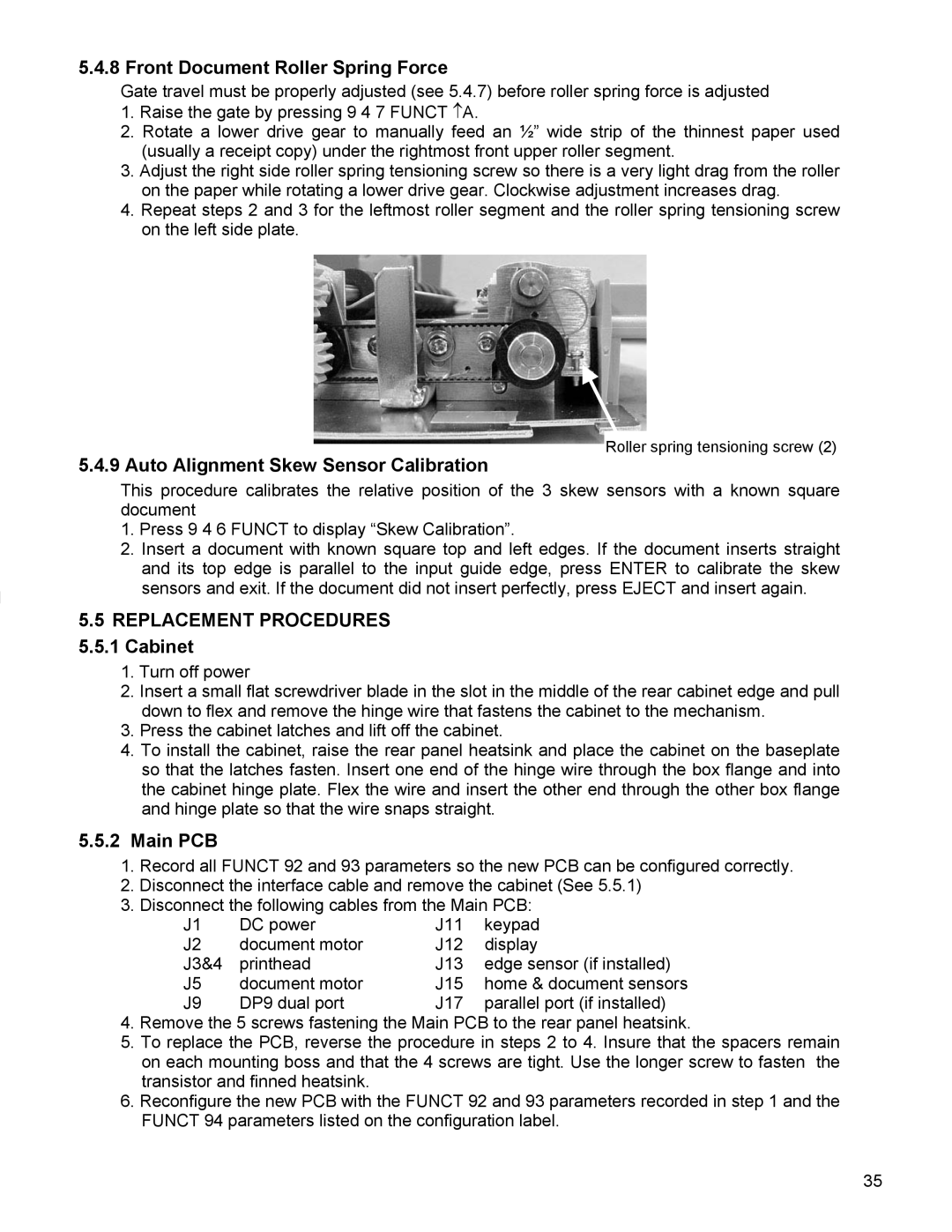
3.Adjust the right side roller spring tensioning screw so there is a very light drag from the roller on the paper while rotating a lower drive gear. Clockwise adjustment increases drag.
4.Repeat steps 2 and 3 for the leftmost roller segment and the roller spring tensioning screw on the left side plate.
5.4.9 Auto Alignment Skew Sensor Calibration
Roller spring tensioning screw (2)
This procedure calibrates the relative position of the 3 skew sensors with a known square document
1.Press 9 4 6 FUNCT to display “Skew Calibration”.
2.Insert a document with known square top and left edges. If the document inserts straight and its top edge is parallel to the input guide edge, press ENTER to calibrate the skew sensors and exit. If the document did not insert perfectly, press EJECT and insert again.
5.5REPLACEMENT PROCEDURES
5.5.1Cabinet
1.Turn off power
2.Insert a small flat screwdriver blade in the slot in the middle of the rear cabinet edge and pull down to flex and remove the hinge wire that fastens the cabinet to the mechanism.
3.Press the cabinet latches and lift off the cabinet.
4.To install the cabinet, raise the rear panel heatsink and place the cabinet on the baseplate so that the latches fasten. Insert one end of the hinge wire through the box flange and into the cabinet hinge plate. Flex the wire and insert the other end through the other box flange and hinge plate so that the wire snaps straight.
5.5.2Main PCB
1.Record all FUNCT 92 and 93 parameters so the new PCB can be configured correctly.
2.Disconnect the interface cable and remove the cabinet (See 5.5.1)
3.Disconnect the following cables from the Main PCB:
J1 | DC power | J11 | keypad |
J2 | document motor | J12 | display |
J3&4 | printhead | J13 | edge sensor (if installed) |
J5 | document motor | J15 | home & document sensors |
J9 | DP9 dual port | J17 | parallel port (if installed) |
4.Remove the 5 screws fastening the Main PCB to the rear panel heatsink.
5.To replace the PCB, reverse the procedure in steps 2 to 4. Insure that the spacers remain on each mounting boss and that the 4 screws are tight. Use the longer screw to fasten the transistor and finned heatsink.
6.Reconfigure the new PCB with the FUNCT 92 and 93 parameters recorded in step 1 and the FUNCT 94 parameters listed on the configuration label.
35