A. GENERAL MAINTENANCE
_, WARNING: Always begin by disconnecting the power supply.
•Periodically check all clamps, nuts, bolts, screws, and belts for tightness and condition. Make sure the throat plate is in good condition and in position.
•Check the blade guard assembly.
•To maintain the table surfaces, fence, and rails, periodically apply paste wax to them and buff to provide smooth functioning. To prevent work from slipping during cutting operation, Do not wax the working face of the miter fence.
•Protect the blade by cleaning out sawdust from underneath the table and in the blade teeth. Use a resin solvent on the blade teeth.
•Clean plastic parts only with a soft damp cloth. Do not use any aerosol or petroleum solvents,
B. SPECIFIC TABLE SAW MAINTENANCE
WARNING: Always begin by disconnecting the power supply.
TO SET BLADE AT 0 OR 45 DEGREES
The angle settings of your saw have been set at the factory and, unless damaged in shipping, should not
require setting during assembly. After extensive use, it may need to be checked.
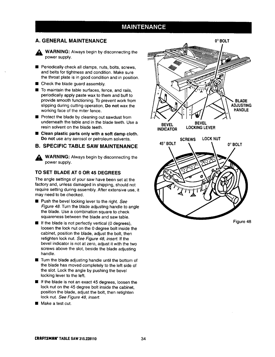
•Push the bevel locking lever to the right. See Figure 48. Turn the blade adjusting handle to angle
the blade. Use a combination square to check squareness between the blade and saw table.
•If the blade is not perfectly vertical (O degrees), loosen the lock nut on the 0 degree bolt inside the cabinet, position the blade, adjust the bolt, then retighten lock nut. See Figure 48, insert. If the bevel indicator is not at zero, adjust it with the two
screws above the slot, beside the blade adjusting handle.
•Turn the blade adjusting handle until the bottom of the blade has moved completely to the left side of the slot. Lock the angle by pushing the bevel locking lever to the left.
•If the blade is not an exact 45 degrees, loosen the lock nut on the 45 degree bolt inside the cabinet, position the blade, adjust the bolt, then retighten lock nut. See Figure 48, insert.
•Make a test cut.
0° BOLT
BLADE
ADJUSTING
HANDLE
BEVELBEVEL
INDICATOR LOCKINGLEVER
SCREWS | LOCKNUT |
45° BOLT | 0° BOLT |
Figure 48