Instructions before first use of this
Rules Operating
Product
Full ONE Year Warranty on Craftsman Table SAW
Rrftsmrn TABLESAW315.228110
21-33
BladeCheckandBladeGuardAssembly
3CRAFTSMANTABLESAW315.228110
Symbol
Safety Alert Symbol
Read ALL Instructions
Do not USE in Dangerous Environ
Never USE this Tool in AN Explosive
Before Making a CUT, be sure all adjust- merits are secure
USE a Support for the Sides and Back
Save These INSTRUCTIONS. Refer to them
Always Push the Workpiece never pull it toward the saw
Speed and Wiring
Extension Cords
Electrical Connection
Grounding Instructions
Resin
Rip Cut
Saw Blade Path
Set
Do not USE 7 in. Wobble Dadoes
Wide Table Kit
Following items are included with your Table Saw
RRAFTSMIIN TABLESAW315.228110
11CRRFTSMRNTABLESAW315.228110
WITH7/16in.SOCKETADJUSTABLE Wrench
L,*.l.,.l,L,J.l,l.,.I,*,l.*,l,,,I.,,I,.l.,,I.i
Socketwrench
Combination Square
Safety Devices
Speed and Wiring
Operating Components
13CRRFTSMRNTABLESAW315.228110
Blade Adjustinghandle Bevel
Know Your Table SAW Bladeguard
Miter Fenceholder Storage Brackets Lockingclamps
Legstand
Off position before plugging tool into the power
Padlock Notprovided
Teeth
Source
Assembling LEG Stand
Leveling feet
Fiat washers 5/16 Hex nuts 5/16-18
NUT LEVELINGFOOT--HEX
Assembling Storage Brackets
Storagebracketsupper Brace Lowerbrace
Legstandassembled Figure
Hexbolt Mounting the LEG Stand on the Table SAW Base
To Install Miter Table and Fence
Endcap Frontrail Scale
RAi
Holdernut
Hole B Tableslot Accessory
To Install Accessory Table and RIP Fence
Lock Lever
To Install Blade Guard
Smallhex
Throatplate
Hexwrench
Grounding
Types of Cuts
Groundingpin Coverofgrounded Outletbox
Motor Cord
CuI-rlNG Tips
CRRFTSI4RNTABLE SAW315.228110
Bevelblade Locking Lever Adjusting Handle
Throatplatebladeguard To Remove the Blade
Innerandouterbladewasher
Large Small HEX Wrench
Loosen Nuts Riving Knife Guard Assembly
Remove the Throat Plate
Tocenterrivingknife
Rearrangeshims Figure
It is weUworth using precautions to avoid the risks
To Reduce Risk of Kickback
To Avoid Kickback
Use these guidelines to avoid kickback
HOW to Make a Featherboard
HOW to Mount a Featherboard
To Make a Push Stick
Featherboard
To Adjust the Blade Depth
To Adjust the Blade Angle
Adjustinghandle RIP Fence
Angledblade
To Lock Miter Table
Miter Slidelock
Making Cuts
To Make a Straight Cross CUT
Blade Miterfence Guardassembly Adjustingclamp
To Make a Straight RIP CUT
Pushstick
Base
To Make a Bevel Cross CUT
Woodeninsert RIP Fence
Bevellockinglever Figure
Do not lock
To Make a Large Panel CUT
Slidingmiteraccessory Tableassemblytable
31CRRFTSMBNTABLESAW315,2281t0
To Make NON-THROUGH Cuts
Inarning Unplug the saw to avoid possible mlury
Raise the saw blade by pushing the bevel locking
Clamp Pushblock Bevellockinglever Figure
To Make Dado Cuts
Unplug your saw
All blades must be rated For at least
RPM
General Maintenance
Indicator Lockinglever Screws Locknut
Blade Adjusting Handle Bevelbevel
Bolt
To Adjust the Bevel Locking Lever
Blade Socketadjustingwheel
To Check the Alignment of the RIP Fence to the Blade
TAB Hexnut CAM Compression
To Adjust the Front and Rear Rail Clamps
To Adjust the Accessory Table
To Align the Miter Locking Clamps
Replace the rails and check the rail cSamps
37CRRFTSMRNTABLESAW315.228110
CRRFTSMRNTABLESAW315.22811038
Eight screws are visible on the miter base B
To Check Miter Fence Alignment
RRIIFTSMIIN TABLESAW315.228110
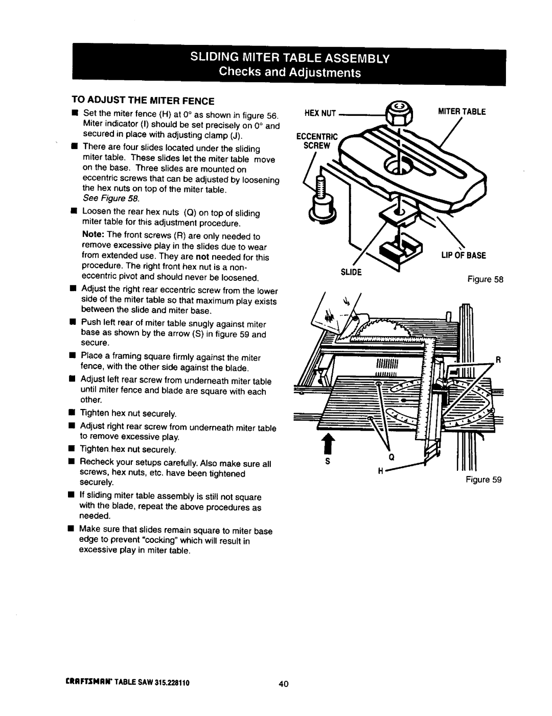
To Adjust the Miter Fence
There are four slides located under the sliding
Hex nuts on top of the miter table
Eccentric Screw UP Ofbase Slide
To Adjust QUICK-STOP
Merindicator Miter Fence Zero
Miter Fence
Degree
Locker Bracket Assembly
Threaded Hole Bevel Gear Backupbracket Washer
Blade Adjusting Handle CRRFTSHRNTABLESAW315.22811042
Tilt / Elevating Mechanism
43rlIAFTSMAW TABLESAW315.228110
Adjust the rivingknife with shims
Sliding miter table assembly does
Not move smoothly Adjusted
Blade is dull
Blade adjusting handle is hard to turn Saw does not start
Saw does not make accurate 90 or 45 degree cuts
Blade makes poor cuts
Motor labors in rip cut
Craftsman 10 in. Table SAW Model no
Forlegstandassembly Referto Rguref
96,100
73 **STD501003 75 *STDe01005
48 **STD600803
Screw
Key Part Number Description Quan
410 Key Part Number Description Quan
Description Quan
661811-001
49CRAFTSMANTABLESAW315.228110
Key Part Number Description Quan
CRAFTSMANTABLESAW315.22811050
Key Part Number
Key Part Number
Standard Hardware Item --May Be Purchased Locally
503
Craftsman 10 in. Table SAW- Model no
Figuref
Parts List for Figure F
KEY Part Number Description Quan
HomeCentralso