PRELIMINARY | CY14B108K, CY14B108M |
|
Switching Waveforms
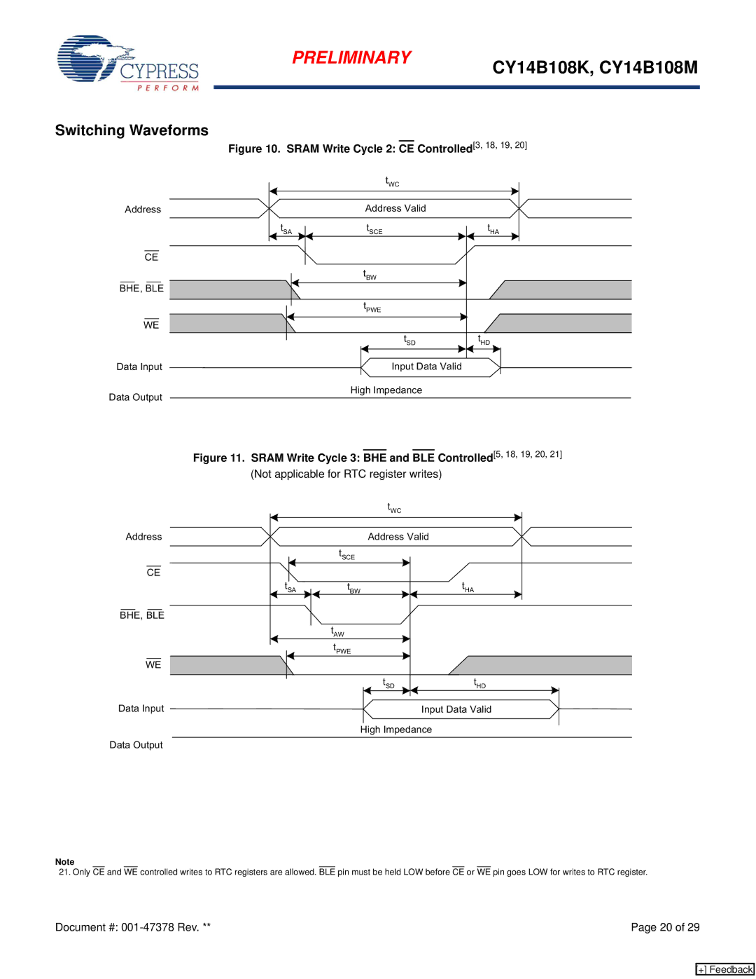
Figure 10. SRAM Write Cycle 2: CE Controlled[3, 18, 19, 20]
Address
CE
BHE, BLE
WE
Data Input
Data Output
| tWC |
|
| Address Valid |
|
tSA | tSCE | tHA |
| tBW |
|
| tPWE |
|
| tSD | tHD |
| Input Data Valid |
|
| High Impedance |
|
Figure 11. SRAM Write Cycle 3: BHE and BLE Controlled[5, 18, 19, 20, 21] | ||
(Not applicable for RTC register writes) |
| |
| tWC |
|
Address | Address Valid |
|
| tSCE |
|
CE |
|
|
tSA | tBW | tHA |
BHE, BLE |
|
|
| tAW |
|
| tPWE |
|
WE |
|
|
| tSD | tHD |
Data Input | Input Data Valid | |
| High Impedance |
|
Data Output |
|
|
Note
21. Only CE and WE controlled writes to RTC registers are allowed. BLE pin must be held LOW before CE or WE pin goes LOW for writes to RTC register.
Document #: | Page 20 of 29 |
[+] Feedback
