14
VS-1200 Data Acccess Switch
3.2Front Panel Description
This section provides a illustration and description of the front panel of the
An explanation of each front panel legend follows:
3.2.1Power
Two switching AC adapter power supplies are provided for each configurable unit. Although only one power supply is required to power the module, use of a second independent power source is strongly recommended to assure uninterrupted monitoring. Furthermore, connecting the second AC input power socket to a different external power source circuit than the first AC input power source eliminates power as a single point of failure. The power barrel sockets are located on the rear.
3.2.2Any-to-Any Ports
Designated as INPUT or OUTPUT by 'Superuser' for use as input or output ports. See Serial and Management Port - Command Line Interface - Superuser Commands - 'SET PORT MONITOR (SE PO MO)' section for more information.
Ports: 1 to 8
Ports: 1 to 4
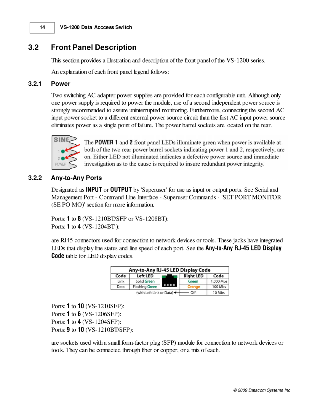
are RJ45 connectors used for connection to network devices or tools. These jacks have integrated LEDs that display line status and line speed of each port. See the
Ports: 1 to 10
Ports: 1 to 6
Ports: 1 to 4
Ports: 9 to 10
are sockets used with a small
© 2009 Datacom Systems Inc
