Hardware Installation
5 Hardware Installation
43
This section describes the
For specific
47' section.
5.1Power
This section describes the power connection at the network installation site of the
or
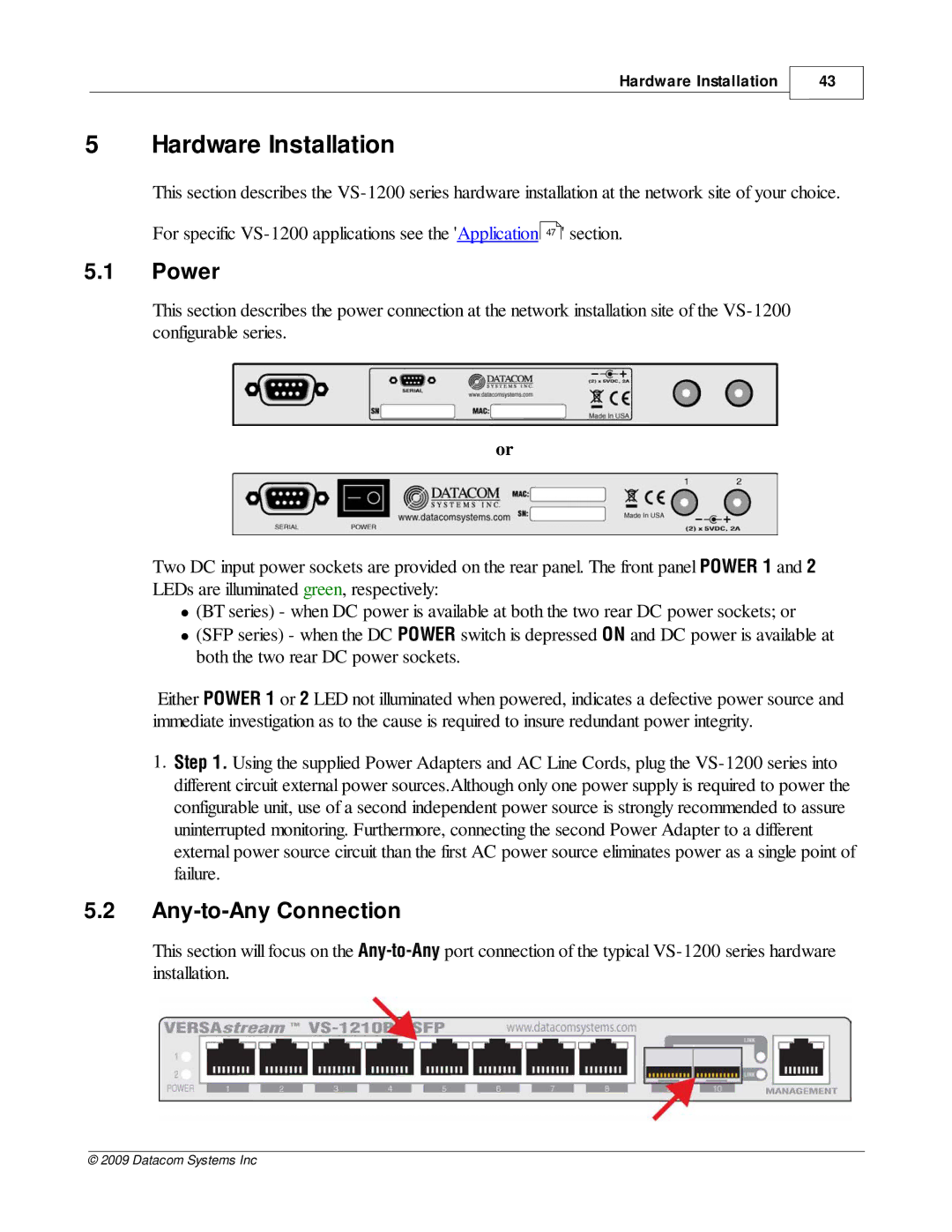
Two DC input power sockets are provided on the rear panel. The front panel POWER 1 and 2 LEDs are illuminated green, respectively:
∙(BT series) - when DC power is available at both the two rear DC power sockets; or
∙(SFP series) - when the DC POWER switch is depressed ON and DC power is available at both the two rear DC power sockets.
Either POWER 1 or 2 LED not illuminated when powered, indicates a defective power source and immediate investigation as to the cause is required to insure redundant power integrity.
1.Step 1. Using the supplied Power Adapters and AC Line Cords, plug the
5.2Any-to-Any Connection
This section will focus on the
installation.
© 2009 Datacom Systems Inc