NOTICE: Ensure that there is a minimum of two inches of space between all vents and any object near these vents.
NOTICE: Keep the vent area clean and
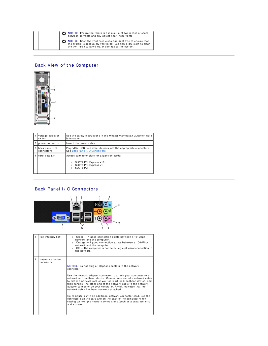
Back View of the Computer
1 | voltage selection | See the safety instructions in the Product Information Guide for more |
|
| switch | information. |
|
2 | power connector | Insert the power cable. |
|
|
|
|
|
3 | back panel I/O | Plug VGA, USB, and other devices into the appropriate connectors. |
|
| connectors | See Back Panel I/O Connectors. |
|
|
|
|
|
4 | card slots (3) | Access connector slots for expansion cards: |
|
|
| • SLOT1 PCI Express x16 |
|
|
| • SLOT2 PCI Express x1 |
|
|
| • SLOT3 PCI |
|
|
|
|
|
|
|
|
|
Back Panel I/O Connectors
1 | link integrity light | • Green — A good connection exists between a |
|
| network and the computer. |
|
| • Orange — A good connection exists between a |
|
| network and the computer. |
|
| • Off — The computer is not detecting a physical connection to |
|
| the network. |
|
|
|
2 | network adapter |
|
| connector |
|
|
| NOTICE: Do not plug a telephone cable into the network |
|
| connector. |
|
| Use the network adapter connector to attach your computer to a |
|
| network or broadband device. Connect one end of a network cable |
|
| to either a network jack or your network or broadband device, and |
|
| then connect the other end of the network cable to the network |
|
| adapter connector on your computer. A click indicates that the |
|
| network cable has been securely attached. |
|
| On computers with an additional network connector card, use the |
|
| connectors on the card and on the back of the computer when |
|
| setting up multiple network connections (such as a separate intra- |
|
| and extranet). |
|
|
|