Dell C510, C610 manual Display-Feed Flex Cable Connector, Remove the center control cover

Models: C510 C610

1 55
Download 55 pages 15.29 Kb
Page 21
Image 21

Display Assembly, Display Latch, and Hinge Covers: Dell Latitude C610/C510 Service Manual

1 M2 x 3-mm screws (4)

2 top cover

3 center control cover

4 M2.5 x 5-mm screws (5)

5 bottom case 6 EMI shield bracket

1.Remove the hard drive.

2.Remove the center control cover.

3.Remove the keyboard.

4.Close the display.

5.From the back of the computer, remove the five M2.5 x 5-mm screws labeled "circle D."

6.Open the display assembly approximately 180 degrees and support the display assembly so that it does not open past this position.

7.Remove the two M2 x 3-mm screws on the EMI shield bracket, which is attached to the display-feed flex cable (see "Display Assembly").

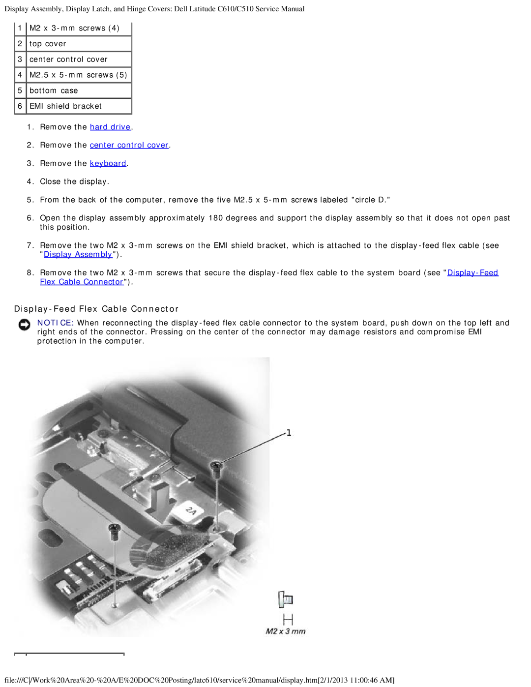
8.Remove the two M2 x 3-mm screws that secure the display-feed flex cable to the system board (see "Display-Feed Flex Cable Connector").

Display-Feed Flex Cable Connector

NOTICE: When reconnecting the display-feed flex cable connector to the system board, push down on the top left and right ends of the connector. Pressing on the center of the connector may damage resistors and compromise EMI protection in the computer.

file:///C/Work%20Area%20-%20A/E%20DOC%20Posting/latc610/service%20manual/display.htm[2/1/2013 11:00:46 AM]

Page 21
Image 21
Dell C510, C610 manual Display-Feed Flex Cable Connector, Remove the center control cover