Display Assembly, Display Latch, and Hinge Covers: Dell Latitude C610/C510 Service Manual
![]() 1
1 ![]() M2 x
M2 x ![]()
9.Pull up on the pull tab that is attached to the
10.Lift the display assembly up and out of the bottom case.
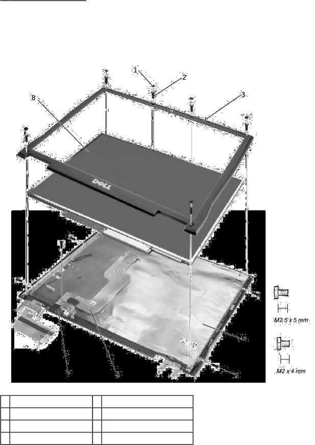
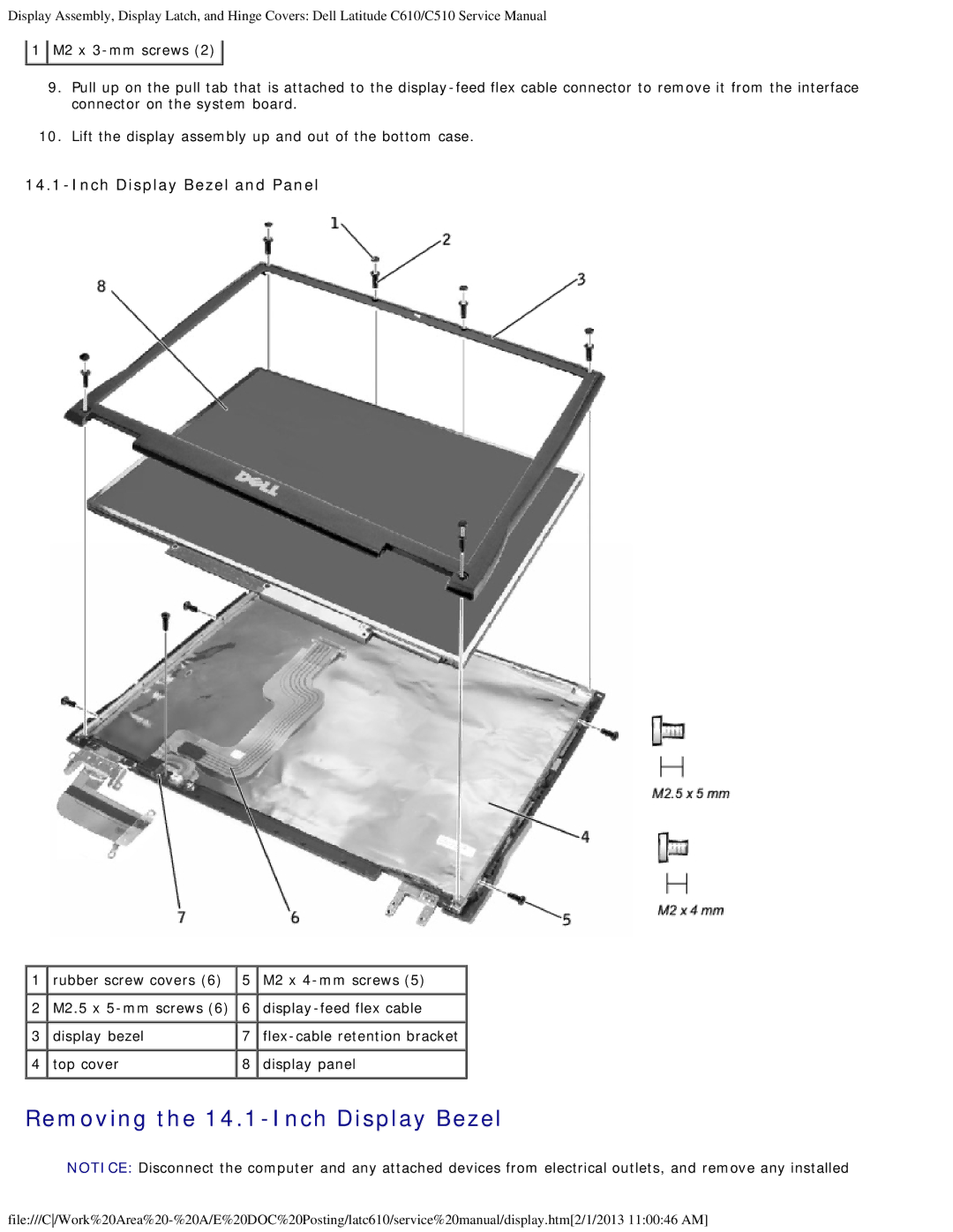
14.1-Inch Display Bezel and Panel
1 | rubber screw covers (6) | 5 | M2 x |
2 | M2.5 x | 6 | |
3 | display bezel | 7 | |
4 | top cover | 8 | display panel |
Removing the 14.1-Inch Display Bezel
NOTICE: Disconnect the computer and any attached devices from electrical outlets, and remove any installed
