Pin Assignments for I/O Connectors: Dell Latitude C610/C510 Service Manual
Back to Contents Page
Pin Assignments for I/O Connectors
Dell™ Latitude™ C610/C510 Service Manual
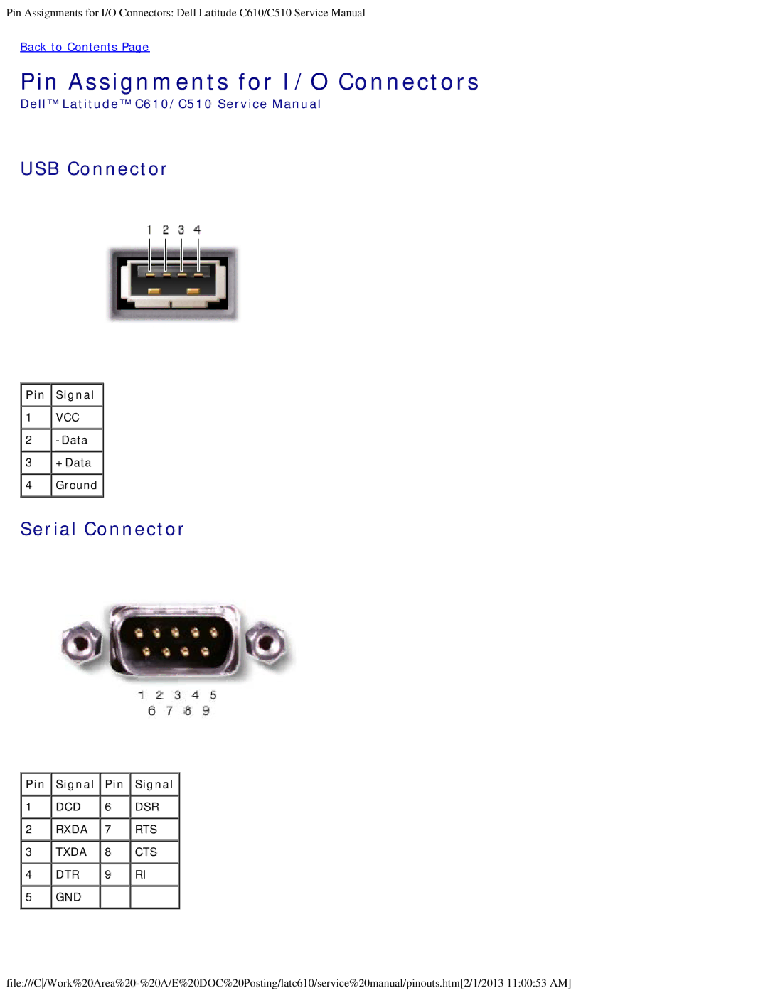
USB Connector
![]() Pin
Pin ![]() Signal
Signal ![]()
1 | VCC |
2 |
|
3 | +Data |
4 | Ground |
Serial Connector
 Pin
Pin  Signal
  Pin
Pin  Signal
1 | DCD | 6 | DSR |
2 | RXDA | 7 | RTS |
3 | TXDA | 8 | CTS |
4 | DTR | 9 | RI |
5 | GND |
|
|