Display Assembly, Display Latch, and Hinge Covers: Dell Latitude C610/C510 Service Manual
Display Latch
NOTICE: Disconnect the computer and any attached devices from electrical outlets, and remove any installed batteries.
NOTICE: To avoid ESD, ground yourself by using a wrist grounding strap or by touching an unpainted metal surface on the computer.
Removing the Display Latch
1.Remove the hard drive.
2.Remove the display assembly.
3.Remove the display bezel.
4.Remove the two M2.5 x
5.Lift the display latch and bracket up and out of the top cover.
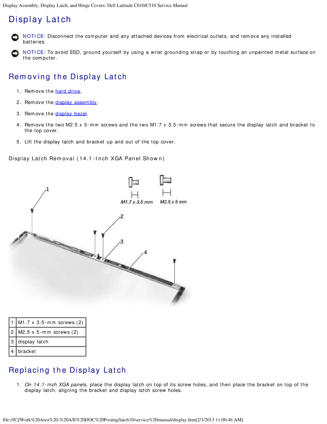
Display Latch Removal (14.1-Inch XGA Panel Shown)
![]() 1
1 ![]() M1.7 x
M1.7 x ![]()
![]() 2
2 ![]() M2.5 x
M2.5 x
![]() 3
3 ![]() display latch
display latch ![]() 4
4 ![]() bracket
bracket
Replacing the Display Latch
1.On