Hardware Owner’s Manual
October
Contents
Main Menu
Enabling and Configuring Console Redirection
Sensor Data Record Other Information You May Need
Main Screen
116
108
111
117
Removing a 3.5-inch Hard-Drive Blank
Installing a Processor
Removing the LSI 9265-8i RAID Battery
Replacing the System Battery
Sensor Boards 300
Minimum Configuration to Post 309
Front Panels 296
334
325
326
335
343
339
340
F11
Accessing System Features during Startup
Keystroke Description
Front-Panel Features and Indicators
About Your System
Or Connector
Indicator, Button Icon Description Or Connector
Green Amber
Hard-Drive Indicator Patterns
Hard-drive activity indicator
Amber Green About Your System
Onboard
Drive on-line Off Controller Blinking When active Fail LSI
Green Amber
Slot Empty Off LSI
SAS
Service Tag
Service Tag Location for 1U Node
11 Service Tag Location on the Left Front Panel
13 Service Tag Linkage
Back Panel Features and Indicators
14 Back Panel with Four System Boards
Due to a problem
System board. Lights amber
System is turned off
System-Board Assembly Configurations
Power button for five seconds
Shutdown, press and hold
19. Enumeration One System Board for 1U Node
Component Indicator Condition
LAN Indicator Codes
Speed indicator Link/activity indicator
23. LAN Indicators Management Port
Or ID Button Press ID Off
Power and System Board Indicator Codes
Status Indicator Codes Component Condition
AC power indicator
Power Supply Indicator Codes
1400W Power Supply
1200W Power Supply
25. Power Supply Status Indicator
BMC Heart Beat LED
BMC heart beat LED
Collecting System Event Log SEL for Investigation
Post Error Code
Error Code Error Message Error Cause Recovery Method
Error Code Error Message Error Cause Recovery Method
Change new
Change processor
Error Device About Your System
Byte Field Value Description
Processor Error
System Event Log
08h Spare
Memory ECC
03h Memory Scrub Failed
Event Data2 XXh Bit
PCI-E Error
IOH Core Error
SB Error
Message System Event, Post starts with Bios
Post Start Event
Post End Event
Post Error Code Event
Bios Recovery Event
Generator ID
ME Fail Event
SEL Generator ID
Sensor Data Record
Record Sensor Sensor Event/Reading Offset Numbe Name Type
Temperature Threshold 01h SI 7Fh SC 68h AM
Temp
01h Temp 0A95h DM 7A95h TM 3838h 000Fh 0x44
08h AM 000Bh DM 000Bh RM 000Bh Dynamic 0xB8
SI 67h SC 40h
08h AM 000Bh DM 000Bh RM 000Bh Dynamic 0xB7
08h AM 000Bh DM 000Bh RM 000Bh Dynamic 0xB9
Fan04h Threshold 01h Variable Dynamic 0xD6
Fan04h Threshold 01h Variable Dynamic 0xD4
Fan04h Threshold 01h Variable Dynamic 0xD5
Fan04h Threshold 01h Variable Dynamic 0xD7
C6220 Fresh Air Support
Expanded Operating Temperature
Other Information You May Need
80W
10 ~ 30 C 35 C 40 C 45 C 60W
70W
95W
115W 12*HDD
10 ~ 30 C 35 C 40 C 45 C
Core
Not support
130W 8 core
130W 4 core
135W 12*HDD
HDD Not support
Mezzanine
1U 1-4 Node 2U 1-2 Node
Full
HDDs 10* HDDs 16* HDDs 24* HDDs
C6220 II Fresh Air Support
35 C 40 C 45 C
24* HDDs 20* HDDs 12* HDDs Full DIMMs
Without
CPU Power
CPU Power 10 ~ 30 C 35 C 40 C 45 C
Micro SD Card Socket Location
Load customized defaults
System Setup Options at Boot
Initiate Setup during Post
Load optimal defaults in Setup menu
Boot Manager
Using the System Setup Program
Console Redirection
Page
BMC Serial Over LAN
Using the System Setup Program
Address Setting
Signal Type Remote
Serial Port Output Access
Option Description
Main Menu
Main Screen
Detected
Displays the MAC address of BMC NIC
Advanced Menu
State 0 default
Power Management
OS Control default
Chassis Power Management
PSU Number
Redundant PSU
Ipmi command
Required Power Supplies
Default is referring from FCB F/W thru BMC by
To run the servers in the chassis
Using the System Setup Program
Using the System Setup Program
Capping value range limits at power budget of PSU
Emergency Throttling
Chassis Level default
Throttling default
CPU Configuration
Using the System Setup Program
Technology in applicable processors
All Cores default
Active Processor Cores
Changing
States
Liability
Operating system
Configures Prefetch. Invisible if CPU do not support
Prefetch Configuration
Cache line in the other half of the sector
Memory Configuration
Optimizer Mode default
Channel
Mirror Mode Enables memory mirroring
System memory available to
For example, in a dual-processor
Enabled for Bios setup to allow users disable
Support low voltage
Sata Configuration
Embedded Sata Controller
Ahci Enables the Sata controller. Sets the device
RAID Enables the Sata controller. Sets the device
Class code as RAID and executes the RAID Option
Enabled if present, Post error if not present
PCI Configuration
Gbps. For power consumption
Onboard Default. Sets PXE boot from on-board NIC
PCIe Generation
Enabled default It is the primary video device
On the Bios search order and system slot layout
Enabled with PXE default
Embedded Network Devices
Enabled without PXE default
Embedded NIC2
Iscsi Remote Boot
Disabled default Using the System Setup Program
Active State Power Management Configuration
PCI-E Link of port11. All entry is disabled
SB. L1 entry is enabled
PCI Slot Configuration
Given PCI-E Link of port11. L1 entry is enabled
USB Configuration
Security Menu
Displayed. If not, Not Installed is displayed
Supervisor Password
If the password has been installed, Installed is
User Password
Enters the Setup utility
Retyped it correctly. If the password confirmation is
Password is required at boot time, or when the user
Stored in Nvram after ezPORT completes.
Server Menu
Immediate default
Shared-NIC default
Set BMC LAN Configuration
Configuration
Remote Access Configuration
115200 8, n, 1 default
COM2 as SOL default
3F8h/2F8h default
Post messages
Boot Menu
Pause on Errors
Compatibility with operating systems that do not
Bios default Firmware Interface Uefi
Exit Menu
Support Uefi
Can be used for this operation
Command Line Interfaces for Setup options
Save Changes and Exit
Discard Changes and Exit
D4 Token Table Setup option Description
Token Setup option Description
If present, Post error if not present
Defaults Boot 00FE Legacy USB
Present, Post error if not present
00D8 Load Optimal
This setting will limit Cpuid function to
Feature is unusable in any OS
This setting disables the 3 or less
Controller SAS controller Using the System Setup Program
019A Power Saving
0199 Power Saving
Features
Enables the I/O Acceleration Technology I/OAT DMA
Setup option Description
124
0250 Quiet Boot
022E Boot Mode
Available Power C States
0251 First NIC is used for PXE boot, followed by NIC2 0252
126
02A9
Disables Dram references from triggering Dram
Memory configuration of the system. This is
Prefetcher Prefetch requests 02AA
128
4035 Serial Port Mode
4033 Serial Port Mode
4034 Serial Port Mode
4036 Serial Port Mode
480E C7 State
Pop up message when the option is changing
480A Cr6 State
4823 Memory
Error is detected on a read transaction
Memory, repairing correctable errors
482A
Link of port. L1 entry enabled
Port. All entry disabled
Link of port. L0s entry enabled
Link of port. L0s and L1 entry enabled
L1 entry enabled
All entry disabled
L0s entry enabled
L0s and L1 entry enabled
Default, Set PXE boot from on-board NIC then Add-on
Entry disabled
Entry enabled
Set PXE boot from Add-on NIC adapter then on-board
Hardware reboot of the motherboard
485E Reboot on WOL
485F Reboot on WOL
Each processor. By default, the maximum number
136
Disables the Acpi Spmi Table for BMC ROM update
48A1
Disables VT-UTF8 Combination Key Support for
Sets BMC LAN to get LAN IP from Static mode
Sets BMC LAN to get LAN IP from Dhcp mode
Enables VT-UTF8 Combination Key Support for
48B4 NMI on Error
Errors occur 48B5 Memory
48DA Save
Diagnostic Tool Boot 48E0
Boot, followed by NIC1
48DF Dell ePSA
48EB
48E9
48EA
48EC
48FA
When Emergency Throttling event trigger
48F9
48FB
Code
Ipmi Command Table Name
Ipmi Device Global Commands
BMC Watchdog Timer Commands
Chassis Device Commands
Sensor Device Commands
Event Commands
PEF and Alerting Commands
SEL Device Commands
FRU Device Commands
SDR Device Commands
Command Forwarding Commands
LAN Device Commands
Serial/Modem Device Commands
Firmware Update Commands
48DC Setup Setting Option Token
Memory Operating 02B6 35V 02B7 Voltage 25V 48B5
Embedded Sata Auto 4834 Gbps 4835 Configuration Link State
Disabled 0199 Enabled 019A
Safety Instructions
Removing and Installing System Components
Opening the System
Recommended Tools
Opening and Closing the System
Closing the System
Traction pad System cover Securing screw
System board assembly
Inside the System
Cooling Fans
Removing a Cooling Fan
Locking clips
Locating pin
Cooling fan Sponge
Fan cable Removing and Installing System Components
Cooling-fan cage
Installing a Cooling Fan
Removing a 3.5-inch Hard-Drive Blank
Installing a 3.5-inch Hard-Drive Blank
Hard Drives
Inch hard-drive blank
Latch
Installing a 2.5-inch Hard-Drive Blank
Removing a 2.5-inch Hard-Drive Blank
Removing a Hard-Drive Carrier
Release button Lock lever Release handle
Installing a Hard-Drive Carrier
Removing a Hard Drive from a Hard-Drive Carrier
Hard-drive carrier Removing and Installing System Components
Adapter Removing and Installing System Components
Installing a Hard Drive into a Hard-Drive Carrier
Installing a 2.5 SSD into a 3.5 Hard-Drive Carrier
SSD
Adapter assembly
Page
PSU and System Board Support Matrix
Power Supplies
Removing a Power Supply
Two System Boards Four System Boards
Handle
Installing a Power Supply
Power supply
Removing and Installing System Components
Retaining latch
System-Board Assembly
Removing a Dummy System-Board Tray
Installing a Dummy System-Board Tray
Removing a System-Board Assembly
Installing a System-Board Assembly
Retaining latch Screw Handle
Air baffle
Air Baffle
Removing the Air Baffle
Installing the Air Baffle
17. Installing the Air Baffle
Heat Sinks
Removing the Heat Sink
19. Removing and Installing the Heat Sink
Removing a Processor
Installing the Heat Sink
Processors
20. Removing and Installing a Processor
Processor shield Notch in processor
Installing a Processor
Removing the Interposer Extender for 2U Node
F10 Save Settings and exit in Bios Setup
Interposer Extender for 2U Node
Installing the Interposer Extender for 2U Node
Interposer-extender tray
Removing and Installing System Components
22. Removing and Installing the Interposer-Extender Tray
Removing the Interposer Extender Tray for 2U Node
Installing the Interposer Extender for 2U Node Tray
Removing the Expansion Card for 1U Node
Expansion-Card Assembly and Expansion Card
Expansion-card assembly
24. Removing the Expansion Card for 1U Node
Expansion-card slot cover Screw Expansion card
Installing the Expansion Card for 1U Node
System-board assembly
Removing the Expansion Card for 2U Node
Expansion-card assembly Screw Expansion-card lock cover
26. Removing the Expansion-card Lock Cover for 2U Node
Riser card Removing and Installing System Components
27. Removing the Expansion Card for 2U Node
28. Installing the Expansion-card Slot Cover for 2U Node
Installing the Expansion Card for 2U Node
Expansion-card bracket
Removing and Installing System Components
PCI-E Slot Priority
RAID Card
Cable Plan
LSI 9265-8i Card
Removing the LSI 9265-8i Card for 1U Node
30. Removing the LSI 9265-8i Card Assembly for 1U Node
LSI 9265-8i-card assembly
31. Removing the LSI 9265-8i Card
Expansion-card slot cover Screw LSI 9265-8i card
Installing the LSI 9265-8i Card for 1U Node
Cable Routing for LSI 9265-8i Card 1U Node
Removing and Installing System Components
33. Cable Routing Down 1U Node
Removing the LSI 9265-8i Card for 2U Node
34. Removing the LSI 9265-8i Card Assembly for 2U Node
35. Removing the LSI 9265-8i Card Lock Cover
36. Removing the LSI 9265-8i Card from the 1.5U Riser Card
LSI 9265-8i card Screw Riser card
Installing the LSI 9265-8i Card for 2U Node
Cable Routing for LSI 9265-8i Card 2U Node
Removing and Installing System Components
38. Cable Routing Down 2U Node
LSI 9265-8i RAID Battery
Removing the LSI 9265-8i RAID battery Assembly
RAID battery assembly Screw
RAID battery tray
Installing the LSI 9265-8i RAID Battery Assembly
Removing the LSI 9265-8i RAID Battery
RAID battery carrier
Installing the LSI 9265-8i RAID Battery
RAID battery Screw
Riser Card
USB connector
PCI-E Gen 3 Removing and Installing System Components
Optional Riser Cards
44 U Riser card for 2U Node
PCI-E Gen 3
45. Removing and Installing the Riser card
Removing the Riser Card for 1U Node
Installing the Riser card for 1U Node
Cable Routing for Riser Card 1U Node
Removing the Riser card for 2U Node
47. Removing and Installing the 1.5U Riser card
Card holder 5U riser card
Installing the Riser card for 2U Node
2U riser card
Cable Routing for Riser Card 2U Node
Optional Mezzanine Cards
Removing the LSI 2008 SAS Mezzanine Card
Installing the LSI 2008 SAS Mezzanine Card
Card bridge card System-board assembly
Cable Routing for LSI 2008 SAS Mezzanine Card 1U Node
Sgpio
Cable Routing for LSI 2008 SAS Mezzanine Card 2U Node
Removing and Installing System Components
Removing and Installing System Components
55. Cable Tie for 2U Node
56. Removing and Installing the Expansion-Card Bracket
Removing the 1GbE Mezzanine Card
57. Removing and Installing the 1GbE mezzanine card assembly
Installing the 1GbE Mezzanine Card
1GbE mezzanine card
Removing the 10GbE Mezzanine Card
59for 1U node. See -25for 2U node
10GbE mezzanine card assembly
Installing the 10GbE Mezzanine Card
10GbE mezzanine card
Mezzanine-Card Bridge Board
Removing the Mezzanine-Card Bridge Board
Installing the Mezzanine-Card Bridge Board
Card bridge board
System Memory
Memory Slot Features
Supported Memory Module Configuration
Memory Module Configurations for Single Processor
63. Dimm Slot Locations
Module Processor Memory
Memory Module Configurations for Dual Processors
Removing the Memory Modules
Module
64. Removing a Memory Module
Memory module
Installing the Memory Modules
65. Installing a Memory Module
Memory module socket ejector
System Battery
Replacing the System Battery
System battery
Negative side of battery connector
System Board
Removing a System Board
67. Removing and Installing the System Board
Installing a System Board
Cable Routing for Onboard Sata Cables 1U Node
69. Cable Routing Down for Onboard Sata Cables 1U Node
Cable Routing for Onboard Sata Cables 2U Node with 3.5 HDDs
Removing and Installing System Components
Cable Routing for Onboard Sata Cables 2U Node with 2.5 HDDs
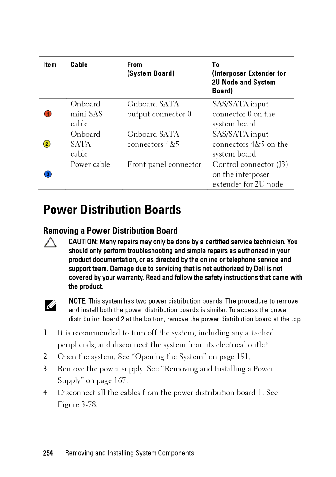
Power Distribution Boards
Removing a Power Distribution Board
73. Removing and Installing the Power Cable Cover
74. Removing and Installing the Power Cables
75. Removing and Installing the Power Distribution Board
Power distribution board
Power distribution board connector
Installing a Power Distribution Board
77. Removing and Installing a Power Distribution Board
Removing and Installing System Components
Cable Routing for Power Distribution Board
78. Cable Routing−Power Distribution Board 1 Top
Cable From Power Distribution Boards
79. Cable Routing−Power Distribution Board 2 Bottom From
Middle Planes
Removing the Middle Planes
80. Removing and Installing the Middle-Wall Bracket
Middle-wall bracket
81. Removing and Installing the Power Cable Cover
82. Removing and Installing the Power Cables
83. Removing and Installing the Upper Middle Plane
84. Removing and Installing the Mid-plane Holder Support
85. Removing and Installing the Mid-plane Holder
Installing the Middle Planes
86. Removing and Installing the Lower Middle Plane
Removing and Installing System Components
Removing and Installing System Components
Removing and Installing System Components
Removing and Installing System Components
Removing and Installing System Components
Cable From Top Middle Plane Direct Backplane
Removing and Installing System Components
Cable From Bottom Middle Plane
Cable From Top Middle Plane Expander Card
Cable From Bottom Middle Plane Expander Card
Direct Backplanes
Removing the Direct Backplane
93. Back View of the 3.5 Direct Backplane
94. Back View of the 2.5 Direct Backplane
Left
95. Removing and Installing the Direct Backplane
Hard-drive cage
Screw Removing and Installing System Components
Installing the Direct Backplane
Removing and Installing System Components
Inch Hard Drive Expander Configuration
Backplane power connector for
Mini-SAS connector 0~3
Power control connector
Mini-SAS connector 12~15
Hard-drive cage
Screw Removing and Installing System Components
Hard-drive cage
Expander card assembly
For Expander Configuration
Removing and Installing System Components
Front Panels
Removing the Front Panel
105. Removing and Installing a Front Panel Assembly
Front-panel assembly
Installing the Front Panel
Retention hooks
Removing and Installing System Components
Sensor Boards
Removing the Sensor Board for 3.5 Hard-Drive System
Installing the Sensor Board for 3.5 Hard-Drive System
Sensor board
Removing and Installing System Components
Panels
Removing the Sensor Board for 2.5 Hard-Drive System
109. Removing and Installing the Sensor Board Assembly
Sensor board assembly
Installing the Sensor Board for 2.5 Hard-Drive System
Sensor-board holder
Removing and Installing System Components
Panels
Troubleshooting Your System
Minimum Configuration to Post
Safety First For You and Your System
Troubleshooting External Connections
Installation Problems
Troubleshooting System Startup Failure
Troubleshooting the Video Subsystem
Troubleshooting a USB Device
Troubleshooting a Serial I/O Device
Troubleshooting a NIC
Troubleshooting a Wet System
Troubleshooting a Damaged System
Troubleshooting the System Battery
Troubleshooting Power Supplies
Troubleshooting System Cooling Problems
Troubleshooting a Fan
Troubleshooting System Memory
Troubleshooting Your System
Troubleshooting a Hard Drive
Troubleshooting a Storage Controller
Troubleshooting Expansion Cards
Troubleshooting Processors
IRQ Assignment Conflicts
Assignment Specific IRQ Requirements IRQ Line
PCI-E Gen3 x16 slot
C6220 II System Board Connectors
Jumpers and Connectors
Serial port Management port LAN connector
C6220 System Board Connectors
Pwrden jumper PCI-E Gen3 x16 slot Ncsi CN connector
Serial port BMC console connector Management port
Backplane Connectors
Hard-Drive Direct Backplane
Bottom To bottom
To bottom
For system board 2 from top to
Hard drive connectors 1 to 6 for
Backplane Jumpers and Connectors
Sgpio connector a for system
Board Sgpio connector a for system
Left to right Configuration
Hard-Drive Expander Backplane
Distribution board
Middle Plane Connectors
Mini-SAS connector for system
Connector 2x9pin power connector
Interposer Extender for 2U Node Connectors
SATA2 and SAS connectors
LSI 2008 SAS Mezzanine Card Connectors
12. LSI 2008 SAS Mezzanine Card Connectors
1GbE Mezzanine Card Connectors
NIC connector Jumpers and Connectors
SFP + port
10GbE Mezzanine Card Connectors
Mezzanine card connector SFP + port Jumpers and Connectors
System board 2
Power Distribution Board 1 Connectors
2x17pin control connector for
Bridge card connector
Power Distribution Board 2 Connectors
Sensor Board Connectors
Power connector
Jumper Settings
Enable Disable
Disable Enable Power Button Pass
Jumper Function Pin1-2 Pin2-3
Direct Backplane Jumper Settings
Contacting Dell
Getting Help
Installing a 2.5-inch SSD into a 2.5-inch adapter bracket
Index
NIC management port, 29 power and system board
Features and indicators front panel
Troubleshooting, 320 heat sink installing
Installing the mezzanine-card bridge board
System battery, 244 riser card for 1U node
Removing the mezzanine-card bridge board
SSD
SAS RAID controller daughter
Troubleshooting