TOP PLATE TO CABINET
NOTE: IF YOUR MACHINE IS SUPPLIED WITH AN LVC STARTER BOX, PLEASE REFER TO THE SUPPLEMENTAL INSTRUCTION SHEET FOR MOUNTING THE LVC BOX TO THE STAND. THEN PROCEED AS FOLLOWS.
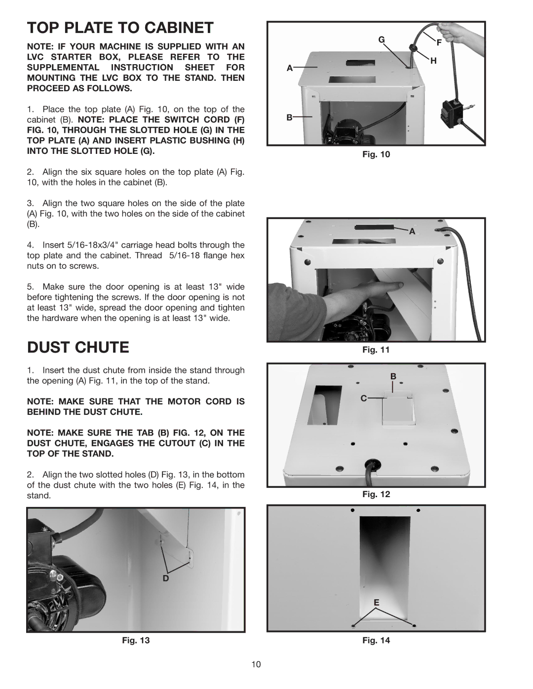
1.Place the top plate (A) Fig. 10, on the top of the cabinet (B). NOTE: PLACE THE SWITCH CORD (F)
FIG. 10, THROUGH THE SLOTTED HOLE (G) IN THE TOP PLATE (A) AND INSERT PLASTIC BUSHING (H) INTO THE SLOTTED HOLE (G).
2.Align the six square holes on the top plate (A) Fig. 10, with the holes in the cabinet (B).
3.Align the two square holes on the side of the plate
(A) Fig. 10, with the two holes on the side of the cabinet
(B).
4.Insert 5/16-18x3/4" carriage head bolts through the top plate and the cabinet. Thread 5/16-18 flange hex nuts on to screws.
5.Make sure the door opening is at least 13" wide before tightening the screws. If the door opening is not at least 13" wide, spread the door opening and tighten the hardware when the opening is at least 13" wide.
DUST CHUTE
1.Insert the dust chute from inside the stand through the opening (A) Fig. 11, in the top of the stand.
NOTE: MAKE SURE THAT THE MOTOR CORD IS BEHIND THE DUST CHUTE.
NOTE: MAKE SURE THE TAB (B) FIG. 12, ON THE DUST CHUTE, ENGAGES THE CUTOUT (C) IN THE TOP OF THE STAND.
2.Align the two slotted holes (D) Fig. 13, in the bottom of the dust chute with the two holes (E) Fig. 14, in the stand.
D
Fig. 13
GF
H
A
B
Fig. 10
![]() A
A
Fig. 11
B
C
Fig. 12
E
Fig. 14
10