BLADE TO SAW
![]() THE 14" BAND SAW USES 93½"
THE 14" BAND SAW USES 93½"
LENGTH BLADES.
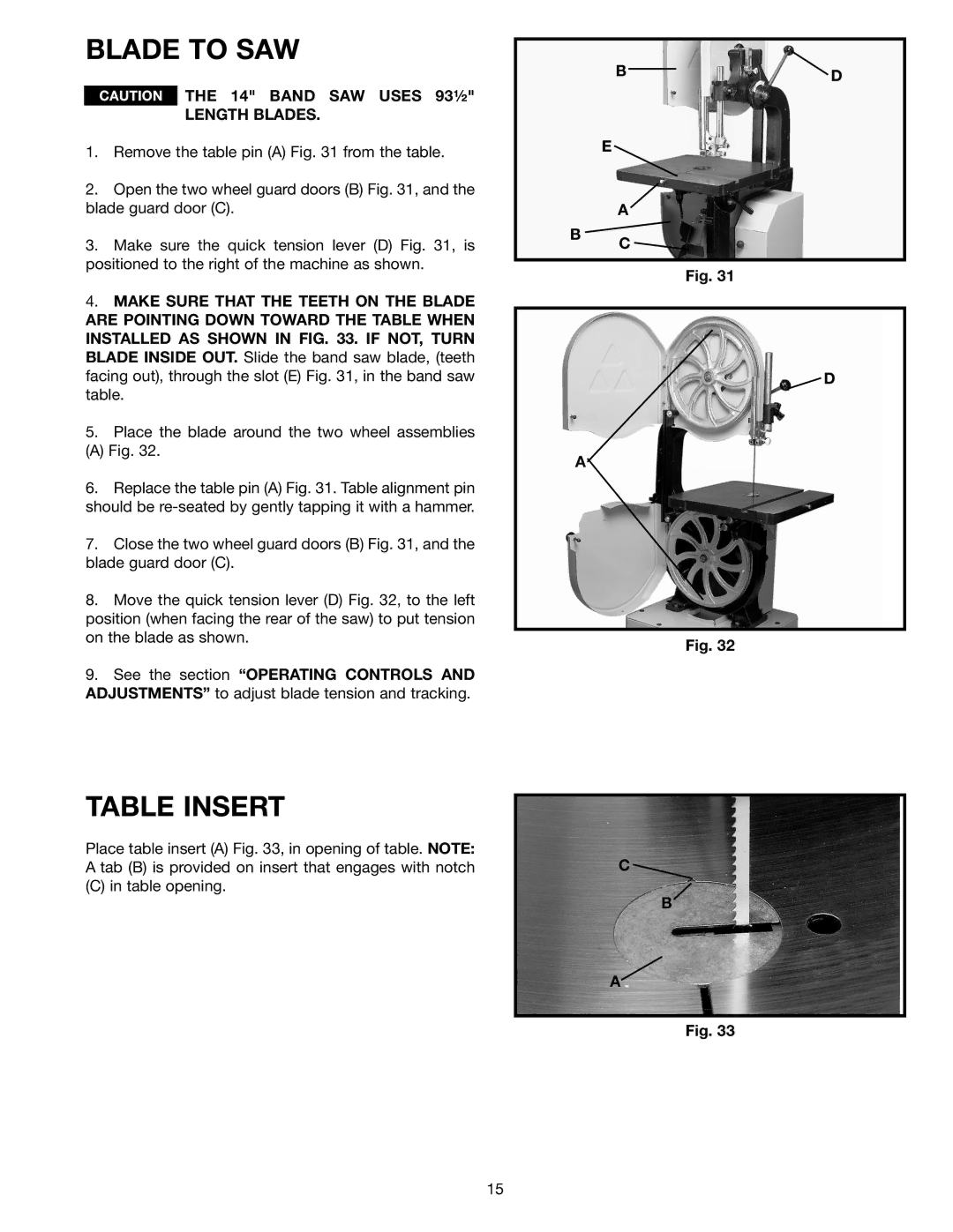
1.Remove the table pin (A) Fig. 31 from the table.
2.Open the two wheel guard doors (B) Fig. 31, and the blade guard door (C).
3.Make sure the quick tension lever (D) Fig. 31, is positioned to the right of the machine as shown.
4.MAKE SURE THAT THE TEETH ON THE BLADE ARE POINTING DOWN TOWARD THE TABLE WHEN INSTALLED AS SHOWN IN FIG. 33. IF NOT, TURN BLADE INSIDE OUT. Slide the band saw blade, (teeth facing out), through the slot (E) Fig. 31, in the band saw table.
5.Place the blade around the two wheel assemblies
(A) Fig. 32.
6.Replace the table pin (A) Fig. 31. Table alignment pin should be
7.Close the two wheel guard doors (B) Fig. 31, and the blade guard door (C).
8.Move the quick tension lever (D) Fig. 32, to the left position (when facing the rear of the saw) to put tension on the blade as shown.
9.See the section “OPERATING CONTROLS AND ADJUSTMENTS” to adjust blade tension and tracking.
TABLE INSERT
Place table insert (A) Fig. 33, in opening of table. NOTE: A tab (B) is provided on insert that engages with notch
(C) in table opening.
B ![]()
![]() D
D
E ![]()
A
B
C
Fig. 31
![]() D
D
A
Fig. 32
C
B
A
Fig. 33
15
