ASSEMBLING BLADE TILTING HANDWHEEL
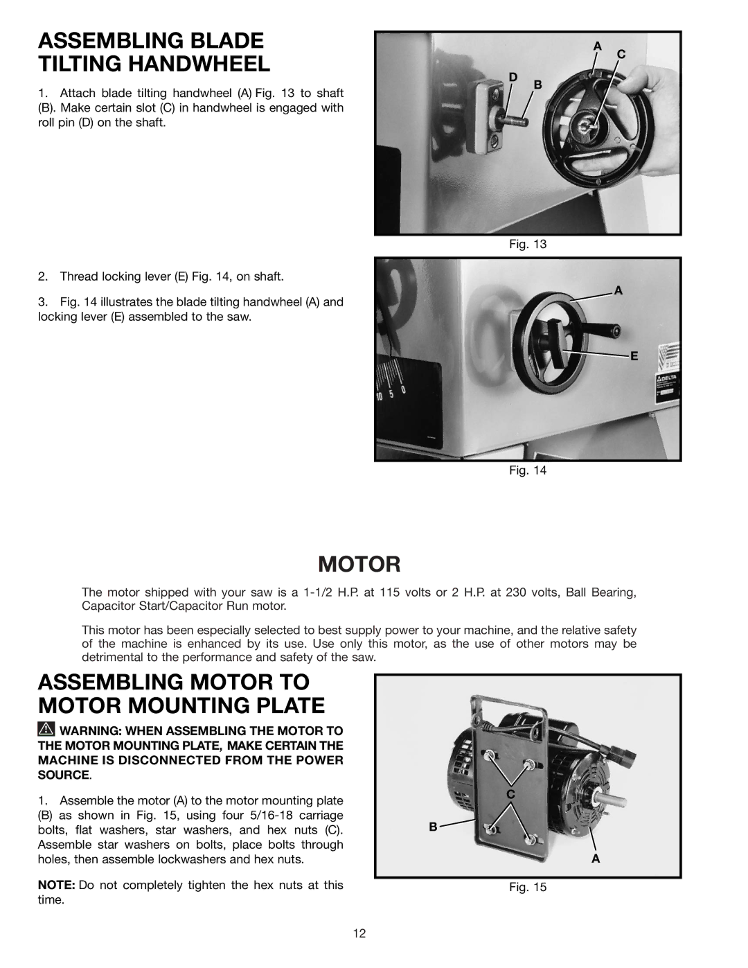
1.Attach blade tilting handwheel (A) Fig. 13 to shaft
(B). Make certain slot (C) in handwheel is engaged with roll pin (D) on the shaft.
D
A
B
C
2.Thread locking lever (E) Fig. 14, on shaft.
3.Fig. 14 illustrates the blade tilting handwheel (A) and locking lever (E) assembled to the saw.
Fig. 13
A
![]() E
E
Fig. 14
MOTOR
The motor shipped with your saw is a
This motor has been especially selected to best supply power to your machine, and the relative safety of the machine is enhanced by its use. Use only this motor, as the use of other motors may be detrimental to the performance and safety of the saw.
ASSEMBLING MOTOR TO MOTOR MOUNTING PLATE
![]() WARNING: WHEN ASSEMBLING THE MOTOR TO THE MOTOR MOUNTING PLATE, MAKE CERTAIN THE MACHINE IS DISCONNECTED FROM THE POWER SOURCE.
WARNING: WHEN ASSEMBLING THE MOTOR TO THE MOTOR MOUNTING PLATE, MAKE CERTAIN THE MACHINE IS DISCONNECTED FROM THE POWER SOURCE.
1.Assemble the motor (A) to the motor mounting plate
(B) as shown in Fig. 15, using four
NOTE: Do not completely tighten the hex nuts at this time.
C
B ![]()
A
Fig. 15
12