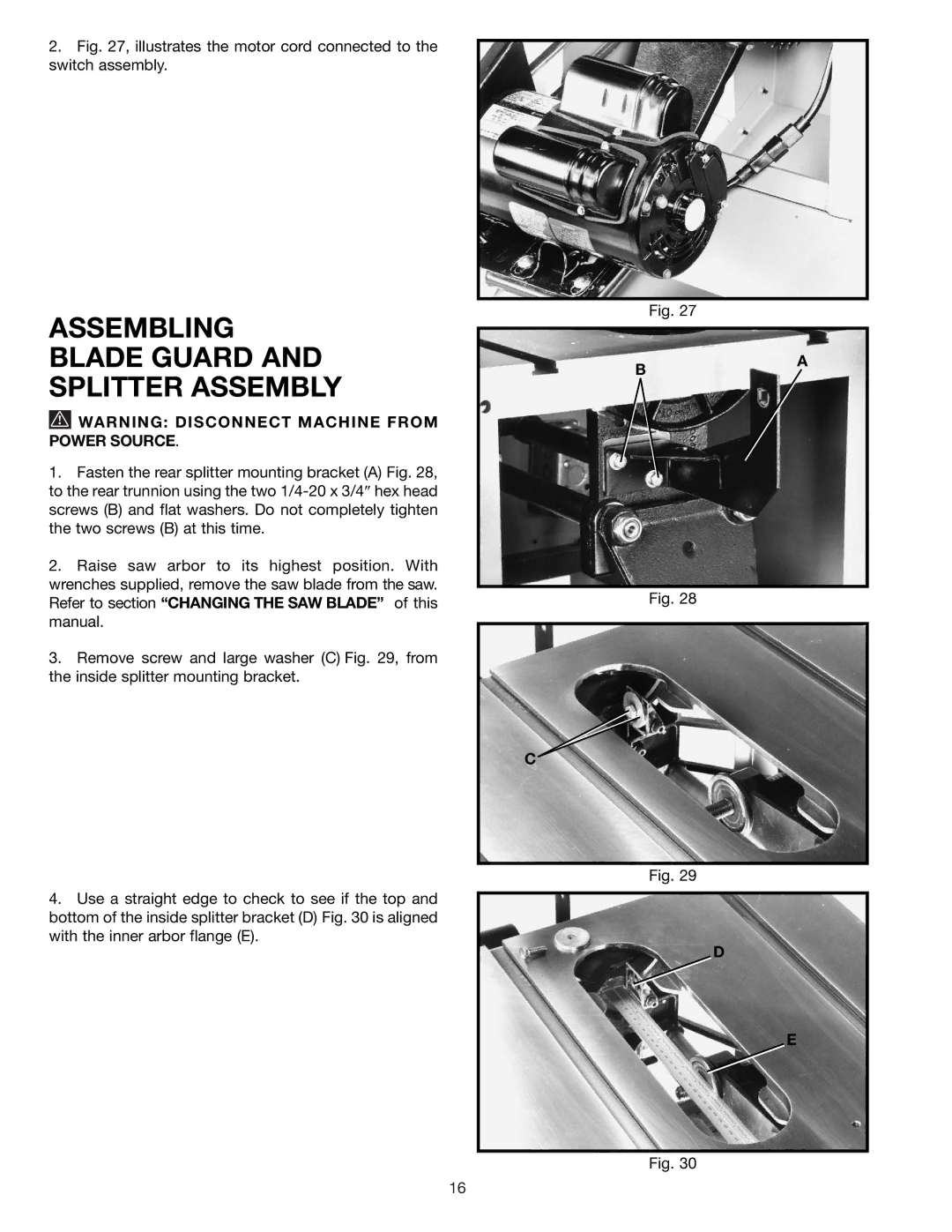
2.Fig. 27, illustrates the motor cord connected to the switch assembly.
Fig. 27
ASSEMBLING BLADE GUARD AND SPLITTER ASSEMBLY
![]() WARNING: DISCONNECT MACHINE FROM POWER SOURCE.
WARNING: DISCONNECT MACHINE FROM POWER SOURCE.
B
A
1.Fasten the rear splitter mounting bracket (A) Fig. 28, to the rear trunnion using the two
2.Raise saw arbor to its highest position. With wrenches supplied, remove the saw blade from the saw. Refer to section “CHANGING THE SAW BLADE” of this manual.
3.Remove screw and large washer (C) Fig. 29, from the inside splitter mounting bracket.
4.Use a straight edge to check to see if the top and bottom of the inside splitter bracket (D) Fig. 30 is aligned with the inner arbor flange (E).
Fig. 28
C
Fig. 29
D
E
Fig. 30
16