DeviceNet Remote I/O Communication Module
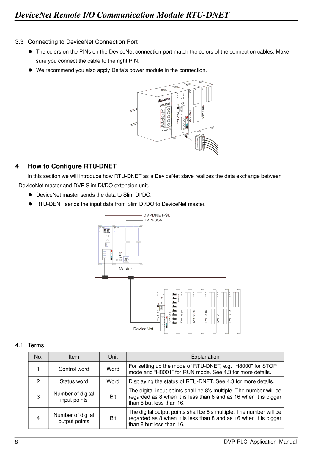
3.3Connecting to DeviceNet Connection Port
z The colors on the PINs on the DeviceNet connection port match the colors of the connection cables. Make sure you connect the cable to the right PIN.
z We recommend you also apply Delta’s power module in the connection.
4 How to Configure RTU-DNET
In this section we will introduce how
zDeviceNet master sends the data to Slim DI/DO.
z
DVP28SV
DVPDNETDVP28SV
RUN
STOP
Master
TE
ND
U-
RT
DeviceNet
![]()
![]() VD
VD ![]()
![]() P- 80 ST
P- 80 ST
![]()
![]() DVP-16SP
DVP-16SP
DA4 0- | CT4 0- | TP4 0- |
PVD | PVD | PVD |
4.1 Terms
No. | Item | Unit | Explanation | |
1 | Control word | Word | For setting up the mode of | |
mode and “H8001” for RUN mode. See 4.3 for more details. | ||||
|
|
| ||
2 | Status word | Word | Displaying the status of | |
|
|
|
| |
3 | Number of digital | Bit | The digital input points shall be 8’s multiple. The number will be | |
regarded as 8 when it is less than 8 and as 16 when it is bigger | ||||
input points | ||||
|
| than 8 but less than 16. | ||
|
|
| ||
|
|
|
| |
4 | Number of digital | Bit | The digital output points shall be 8’s multiple. The number will be | |
regarded as 8 when it is less than 8 and as 16 when it is bigger | ||||
output points | ||||
|
| than 8 but less than 16. | ||
|
|
| ||
|
|
|
|
8 |