DeviceNet Remote I/O Communication Module
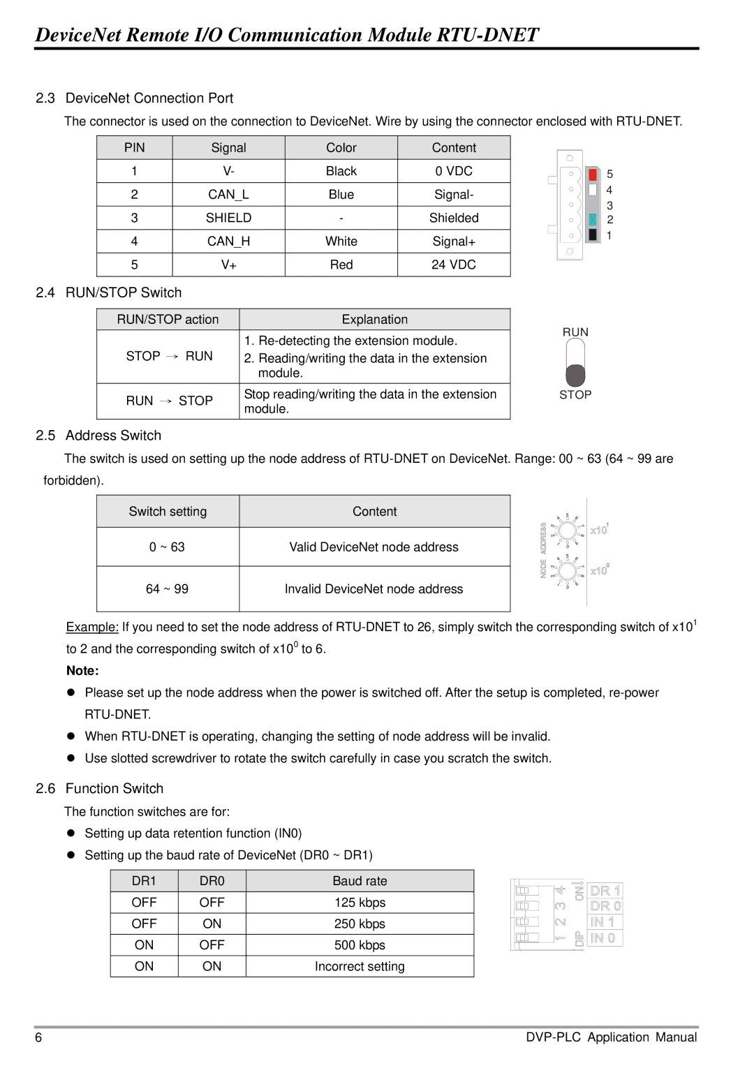
2.3DeviceNet Connection Port
The connector is used on the connection to DeviceNet. Wire by using the connector enclosed with
PIN | Signal | Color | Content |
|
1 | V- | Black | 0 VDC | 5 |
2 | CAN_L | Blue | Signal- | 4 |
3 | SHIELD | - | Shielded | 3 |
2 | ||||
4 | CAN_H | White | Signal+ | 1 |
| ||||
5 | V+ | Red | 24 VDC |
|
2.4 RUN/STOP Switch
RUN/STOP action |
| Explanation | RUN | |
STOP → RUN | 1. | |||
| ||||
2. | Reading/writing the data in the extension |
| ||
|
| module. |
| |
RUN → STOP | Stop reading/writing the data in the extension | STOP | ||
module. |
| |||
|
| |||
2.5 Address Switch
The switch is used on setting up the node address of
Switch setting | Content |
|
|
0 ~ 63 | Valid DeviceNet node address |
|
|
64 ~ 99 | Invalid DeviceNet node address |
|
|
5
4 3
2 |
|
1 | 0 |
| |
4 | 5 |
| |
3 |
|
2 |
|
1 | 0 |
|
6
7
8 9
6
7
8 9
Example: If you need to set the node address of
Note:
zPlease set up the node address when the power is switched off. After the setup is completed,
zWhen
zUse slotted screwdriver to rotate the switch carefully in case you scratch the switch.
2.6Function Switch
The function switches are for:
zSetting up data retention function (IN0)
zSetting up the baud rate of DeviceNet (DR0 ~ DR1)
DR1 | DR0 | Baud rate |
OFF | OFF | 125 kbps |
|
|
|
OFF | ON | 250 kbps |
|
|
|
ON | OFF | 500 kbps |
ON | ON | Incorrect setting |
|
|
|
6 |