Connecting video components
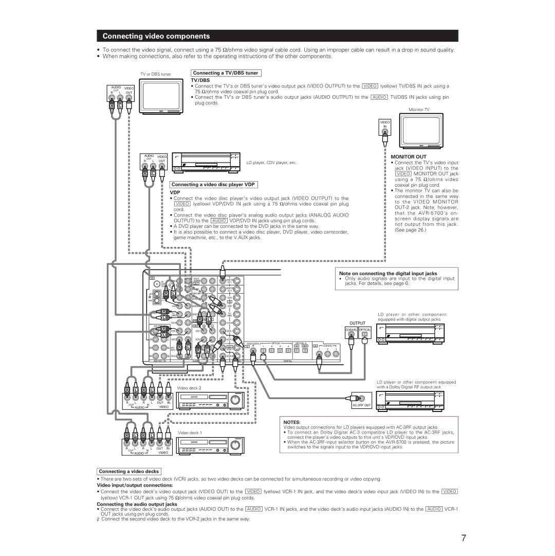
•To connect the video signal, connect using a 75 Ω /ohms video signal cable cord. Using an improper cable can result in a drop in sound quality.
•When making connections, also refer to the operating instructions of the other components.
TV or DBS tuner
AUDIO VIDEO
OUT
R L OUT
R | L |
Connecting a TV/DBS tuner
TV/DBS
•Connect the TV’s or DBS tuner’s video output jack (VIDEO OUTPUT) to the VIDEO (yellow) TV/DBS IN jack using a 75 Ω /ohms video coaxial pin plug cord.
•Connect the TV’s or DBS tuner’s audio output jacks (AUDIO OUTPUT) to the AUDIO TV/DBS IN jacks using pin plug cords.
Monitor TV
VIDEO
IN
AUDIO | VIDEO |
| |
| OUT |
| |
R |
|
| |
L OUT | LD player, CDV player, etc. | ||
|
|
| |
R | L |
|
|
Connecting a video disc player VDP
VDP
•Connect the video disc player’s video output jack (VIDEO OUTPUT) to the VIDEO (yellow) VDP/DVD IN jack using a 75 Ω /ohms video coaxial pin plug
cord.
•Connect the video disc player’s analog audio output jacks (ANALOG AUDIO OUTPUT) to the AUDIO VDP/DVD IN jacks using pin plug cords.
•A DVD player can be connected to the DVD jacks in the same way.
•It is also possible to connect a video disc player, DVD player, video camcorder, game machine, etc., to the V.AUX jacks.
MONITOR OUT
•Connect the TV’s video input jack (VIDEO INPUT) to the
VIDEO MONITOR OUT jack using a 75 Ω /ohms video coaxial pin plug cord.
•The monitor TV can also be connected in the same way to the VIDEO MONITOR
IN | PHONO |
| |
FM |
| ||
COAX. |
| R | L |
75 |
| ||
|
|
| |
| SIGNAL CD |
| |
| GND | L |
|
R |
| ||
LOOP | DVD |
| |
ANT. |
|
| |
AM |
|
|
|
|
| VDP |
|
R |
| TV/ |
|
ANTENNA TERMINALS |
| ||
L |
| DBS |
|
|
|
| |
|
| V.AUX |
|
6CH EXT. IN |
|
|
|
R | FL |
| |
FR |
| ||
L |
|
|
|
SW | C |
| |
SR | SL MD/ R | L |
|
| |
ER | EL |
|
| 8CH EXT. IN |
|
MULTI |
| MONITOR |
SOURCE |
| |
| ||
OUT |
| |
|
| |
FRONT |
| MONITOR |
| ||
CENTER |
| |
|
| |
SUB |
| DVD |
WOOFER |
| |
|
| |
|
| IN |
SURROUND |
| VDP |
EFECT |
| TV/ |
| DBS | |
|
| |
R | R | L L |
PREOUT | V.AUX | |
OUT | R | L |
| ||
MD/ |
| OUT |
L | ||
R |
| |
| ||
AUDIO | VIDEO |
DOLBY DIGITAL |
|
| OPTICAL |
|
| |||||
IN | RF | 1 | 2 | 3 | 4 | |||||
|
|
|
|
|
|
|
|
|
|
|
|
|
|
|
|
|
|
|
|
|
|
DIGITAL
IN ![]()
![]() OUT
OUT
Note on connecting the digital input jacks
•Only audio signals are input to the digital input jacks. For details, see page 6.
LD player or other component equipped with digital output jacks
OUTPUT
COAXIAL OPTICAL
IN ![]()
![]() COAXIAL
COAXIAL ![]()
1 2 3
R | L | R | L | Video deck 2 |
|
R |
|
| L | R |
| L OUT IN |
| OUT |
| IN | |||
|
|
| AUDIO |
| VIDEO | |
|
|
|
| |||
R | L | R | Video deck 1 |
L |
R |
|
| L | R |
| L OUT IN |
| OUT |
| IN | |||
|
|
| AUDIO |
| VIDEO | |
|
|
|
| |||
LD player or other component equipped with a Dolby Digital RF output jack
NOTES:
Video output connections for LD players equipped with
•To connect an Dolby Digital
•When the
Connecting a video decks
•There are two sets of video deck (VCR) jacks, so two video decks can be connected for simultaneous recording or video copying.
Video input/output connections:
•Connect the video deck’s video output jack (VIDEO OUT) to the VIDEO (yellow)
Connecting the audio output jacks
•Connect the video deck’s audio output jacks (AUDIO OUT) to the AUDIO
2Connect the second video deck to the
VIDEO
7