ENGLISH
4
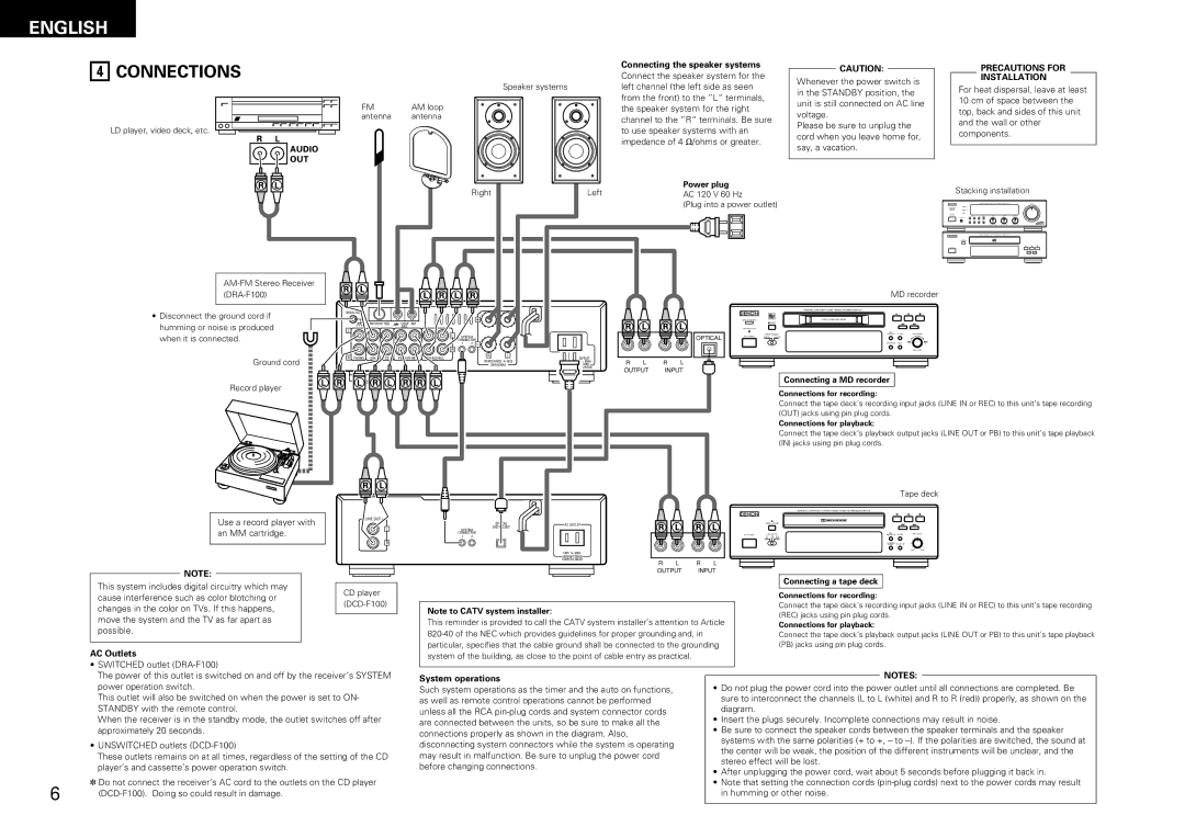
CONNECTIONS
LD player, video deck, etc.
FM | AM loop |
antenna | antenna |
| Connecting the speaker systems |
| Connect the speaker system for the |
Speaker systems | left channel (the left side as seen |
| from the front) to the ”L“ terminals, |
| the speaker system for the right |
| channel to the ”R“ terminals. Be sure |
| to use speaker systems with an |
| impedance of 4 Ω /ohms or greater. |
CAUTION:
Whenever the power switch is in the STANDBY position, the unit is still connected on AC line voltage.
Please be sure to unplug the cord when you leave home for, say, a vacation.
PRECAUTIONS FOR
INSTALLATION
For heat dispersal, leave at least 10 cm of space between the top, back and sides of this unit and the wall or other components.
|
|
|
|
|
|
| Right |
| Left |
|
|
| Power plug |
|
|
|
|
|
|
|
| Stacking installation |
|
|
|
|
|
|
|
|
|
|
|
| AC 120 V 60 Hz |
|
|
|
|
|
|
|
| ||||
|
|
|
|
|
|
|
|
|
|
|
|
| (Plug into a power outlet) |
|
|
|
|
| B |
| |||
|
|
|
|
|
|
|
|
|
|
|
|
|
|
|
|
|
|
|
|
|
| B |
|
|
|
|
|
|
|
|
|
|
|
|
|
|
|
|
|
|
|
|
|
|
| / | / |
|
|
|
|
|
|
|
|
|
|
|
|
|
|
|
|
|
|
|
|
|
|
| |
|
|
|
|
|
|
|
|
|
|
|
|
|
|
|
|
|
|
| MD recorder |
| |||
• Disconnect the ground cord if | SIGNAL GND |
|
|
|
|
|
|
|
|
|
|
|
|
|
| PERSONAL COMPONENT SYSTEM / MINIDISC RECORDER |
|
|
|
| |||
|
|
|
|
|
|
|
|
|
|
| B |
|
|
|
|
| 1 | 3 |
|
| |||
|
|
|
|
|
|
|
|
|
|
|
|
| REMOTE SENSOR |
|
|
|
| POWER LOADING MECHANISM |
|
|
|
| |
humming or noise is produced | L |
| FM COAX 75º | LOOP AM |
|
|
|
|
|
|
|
|
|
| EJECT |
|
|
| REC / |
|
|
| |
|
|
| ANT. |
|
|
|
|
|
|
|
| PICK REC MODE |
|
|
|
|
|
|
|
| |||
when it is connected. |
|
|
|
| L | CONNECTOR |
|
|
|
|
| OPTICAL |
| INPUT SELECT |
|
| R | PICK REC CD SRS |
| PUSH ENTER |
| ||
|
|
|
|
| SYSTEM |
|
|
|
|
|
| ON / STANDBY | DIGITAL | ANALOG |
| D.IN | 1 L |
|
|
|
| ||
|
|
|
|
|
| 1 | 2 |
|
|
|
|
|
|
|
|
|
| 04Tr 12m 48s | CHARACTER EDIT | - | + |
| |
|
|
|
|
| R |
|
|
|
|
|
|
|
|
| 1 | 2 | RANDOM |
|
|
|
| ||
|
|
|
|
|
|
|
|
|
|
|
|
|
|
|
|
|
|
|
|
| REC LEVEL |
| |
Ground cord | R | PHONO | AUX | CD |
| R | L | AC OUTLET |
|
|
|
|
|
|
|
|
|
|
|
|
|
| |
| SPEAKERS |
| R | L | R | L |
|
|
|
|
|
|
|
|
|
| |||||||
|
|
|
|
|
|
| SWITCHED |
|
|
|
|
|
|
|
|
|
| ||||||
|
|
|
|
|
|
| IMPEDANCE 4~16º | 120V 60Hz |
|
|
|
|
|
|
|
|
|
|
|
|
|
| |
|
|
|
|
|
|
|
|
| 120W(1A.)MAX | OUTPUT | INPUT |
|
|
|
|
|
|
|
|
|
| ||
|
|
|
|
|
|
|
|
|
|
|
|
|
|
|
|
|
|
|
| ||||
Record player |
|
|
|
|
|
|
|
|
|
|
|
|
|
|
|
| Connecting a MD recorder |
|
|
| |||
|
|
|
|
|
|
|
|
|
|
|
|
|
|
| Connections for recording: |
|
|
|
| ||||
|
|
|
|
|
|
|
|
|
|
|
|
|
|
|
|
|
|
|
| ||||
|
|
|
|
|
|
|
|
|
|
|
|
|
|
|
| Connect the tape deck’s recording input jacks (LINE IN or REC) to this unit’s tape recording | |||||||
|
|
|
|
|
|
|
|
|
|
|
|
|
|
|
| (OUT) jacks using pin plug cords. |
|
|
| ||||
|
|
|
|
|
|
|
|
|
|
|
|
|
|
|
| Connections for playback: |
|
|
|
| |||
|
|
|
|
|
|
|
|
|
|
|
|
|
|
|
| Connect the tape deck’s playback output jacks (LINE OUT or PB) to this unit’s tape playback | |||||||
|
|
|
|
|
|
|
|
|
|
|
|
|
|
|
| (IN) jacks using pin plug cords. |
|
|
|
| |||
Use a record player with an MM cartridge.
NOTE:
This system includes digital circuitry which may cause interference such as color blotching or changes in the color on TVs. If this happens, move the system and the TV as far apart as possible.
LINE OUT
L
R
CD player (DCD-F100)
|
|
|
|
|
|
|
|
|
|
|
|
|
|
|
|
|
|
|
|
|
|
|
|
|
|
|
|
|
|
|
|
|
|
|
|
|
|
|
|
|
|
|
|
|
|
|
|
|
|
|
|
|
|
|
|
|
|
| OPTICAL |
|
| AC OUTLET | |||||||
|
|
|
|
| |||||||||
|
|
| DIGITAL OUT |
|
|
|
|
| |||||
|
| SYSTEM |
|
|
|
|
| ||||||
|
| CONNECTOR |
|
|
|
|
|
|
| ||||
| 1 | 2 |
|
|
|
|
|
|
|
|
|
| |
|
|
|
|
|
|
|
|
|
|
|
|
|
|
|
|
|
|
|
|
|
|
|
|
|
|
|
|
120V ![]() 60Hz
60Hz
UNSWITCHED 120W(1A.)MAX
R L R L
OUTPUT INPUT
Note to CATV system installer:
This reminder is provided to call the CATV system installer’s attention to Article
Tape deck
PERSONAL COMPONENT SYSTEM / STEREO CASSETTE TAPE DECK
B![]()
![]()
OPEN / CLOSE
| REV. MODE |
| REC/ | CD SRS | REC LEVEL | |
ON / STANDBY |
| REC MUTE | ||||
|
| dB |
|
|
| |
|
| L |
|
|
|
|
|
| R | COUNTER | DOLBY NR |
|
|
|
| RESET |
|
| ||
| TAPE | B | PLAY |
|
|
|
|
|
|
|
| MIN | MAX |
Connecting a tape deck
Connections for recording:
Connect the tape deck’s recording input jacks (LINE IN or REC) to this unit’s tape recording (REC) jacks using pin plug cords.
Connections for playback:
Connect the tape deck’s playback output jacks (LINE OUT or PB) to this unit’s tape playback (PB) jacks using pin plug cords.
AC Outlets
system of the building, as close to the point of cable entry as practical.
•SWITCHED outlet
The power of this outlet is switched on and off by the receiver’s SYSTEM power operation switch.
This outlet will also be switched on when the power is set to ON- STANDBY with the remote control.
When the receiver is in the standby mode, the outlet switches off after approximately 20 seconds.
•UNSWITCHED outlets
These outlets remains on at all times, regardless of the setting of the CD player’s and cassette’s power operation switch.
✽Do not connect the receiver’s AC cord to the outlets on the CD player
6 | |
|
System operations
Such system operations as the timer and the auto on functions, as well as remote control operations cannot be performed unless all the RCA
NOTES:
•Do not plug the power cord into the power outlet until all connections are completed. Be sure to interconnect the channels (L to L (white) and R to R (red)) properly, as shown on the diagram.
•Insert the plugs securely. Incomplete connections may result in noise.
•Be sure to connect the speaker cords between the speaker terminals and the speaker systems with the same polarities (+ to +, – to
•After unplugging the power cord, wait about 5 seconds before plugging it back in.
•Note that setting the connection cords