VENTING INSTALLATION (Cont) | 8 |
CHECKING FOR PROPER VENTING |
VENTING INSTALLATION Continued
Example 1: Shows the minimum allowable system height and lateral offset for a 60° degrees or greater inclination. Code specifies that offsets at 60° degrees or greater are considered horizontal and must follow the 75% percent rule for lateral to total certical system height. Codes also allows only one offset in the total system when at 60° degrees or greater. The total vertical height in this example represents the minimum height of 8 feet and therefore the allowable lateral is 6 feet when the 75% percent rule applies. If the lateral length must exceed 75% then the system must be sized in accor- dance with the Category I venting tables.
Example 2: Shows multiple offsets each at 45° degrees of inclina- tion. Multiple offsets are permitted if they do not exceed 45° degrees of inclination. The total lengths of the two offsets are not required to meet the 75% percent rule.
Example 3: Shows a single offset at 45° degrees of inclination and therefore the lateral length at 10 feet of offset does not have to meet the 75% percent allowable rule.
In each case the offsets must be supported and firestops must be positioned wherever the vent must pass through a
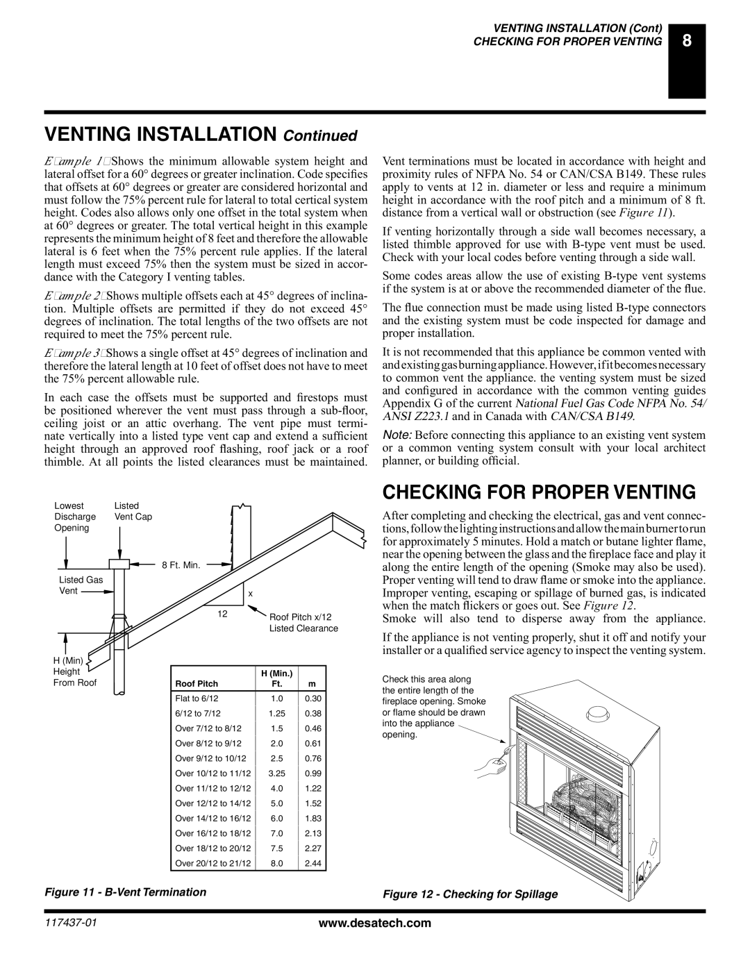
Vent terminations must be located in accordance with height and proximity rules of NFPA No. 54 or CAN/CSA B149. These rules apply to vents at 12 in. diameter or less and require a minimum height in accordance with the roof pitch and a minimum of 8 ft. distance from a vertical wall or obstruction (see Figure 11).
If venting horizontally through a side wall becomes necessary, a listed thimble approved for use with
Some codes areas allow the use of existing
The flue connection must be made using listed
It is not recommended that this appliance be common vented with andexistinggasburningappliance.However,ifitbecomesnecessary to common vent the appliance. the venting system must be sized and configured in accordance with the common venting guides Appendix G of the current National Fuel Gas Code NFPA No. 54/ ANSI Z223.1 and in Canada with CAN/CSA B149.
Note: Before connecting this appliance to an existing vent system or a common venting system consult with your local architect planner, or building official.
Lowest | Listed |
|
|
| |
Discharge | Vent Cap |
|
|
| |
Opening |
|
|
|
|
|
| 8 Ft. Min. |
|
|
| |
|
|
|
| ||
Listed Gas |
|
|
|
|
|
Vent |
| x |
|
|
|
|
|
|
|
| |
| 12 | Roof Pitch x/12 | |||
|
|
| |||
|
|
| Listed Clearance | ||
H (Min) |
|
|
|
|
|
Height |
|
| H (Min.) |
|
|
From Roof |
| Roof Pitch | Ft. | m |
|
|
|
|
|
|
|
|
| Flat to 6/12 | 1.0 | 0.30 |
|
|
| 6/12 to 7/12 |
|
|
|
|
| 1.25 | 0.38 |
| |
|
| Over 7/12 to 8/12 |
|
|
|
|
| 1.5 | 0.46 |
| |
|
| Over 8/12 to 9/12 |
|
|
|
|
| 2.0 | 0.61 |
| |
|
| Over 9/12 to 10/12 |
|
|
|
|
| 2.5 | 0.76 |
| |
|
| Over 10/12 to 11/12 |
|
|
|
|
| 3.25 | 0.99 |
| |
|
| Over 11/12 to 12/12 |
|
|
|
|
| 4.0 | 1.22 |
| |
|
| Over 12/12 to 14/12 |
|
|
|
|
| 5.0 | 1.52 |
| |
|
| Over 14/12 to 16/12 |
|
|
|
|
| 6.0 | 1.83 |
| |
|
| Over 16/12 to 18/12 |
|
|
|
|
| 7.0 | 2.13 |
| |
|
| Over 18/12 to 20/12 |
|
|
|
|
| 7.5 | 2.27 |
| |
|
| Over 20/12 to 21/12 |
|
|
|
|
| 8.0 | 2.44 |
| |
|
|
|
|
|
|
CHECKING FOR PROPER VENTING
After completing and checking the electrical, gas and vent connec- tions,followthelightinginstructionsandallowthemainburnertorun for approximately 5 minutes. Hold a match or butane lighter flame, near the opening between the glass and the fireplace face and play it along the entire length of the opening (Smoke may also be used). Proper venting will tend to draw flame or smoke into the appliance. Improper venting, escaping or spillage of burned gas, is indicated when the match flickers or goes out. See Figure 12.
Smoke will also tend to disperse away from the appliance.
If the appliance is not venting properly, shut it off and notify your installer or a qualified service agency to inspect the venting system.
Check this area along the entire length of the fireplace opening. Smoke or flame should be drawn into the appliance opening.
Figure 11 - | Figure 12 - Checking for Spillage |
www.desatech.com |