2
Hardware Installation 


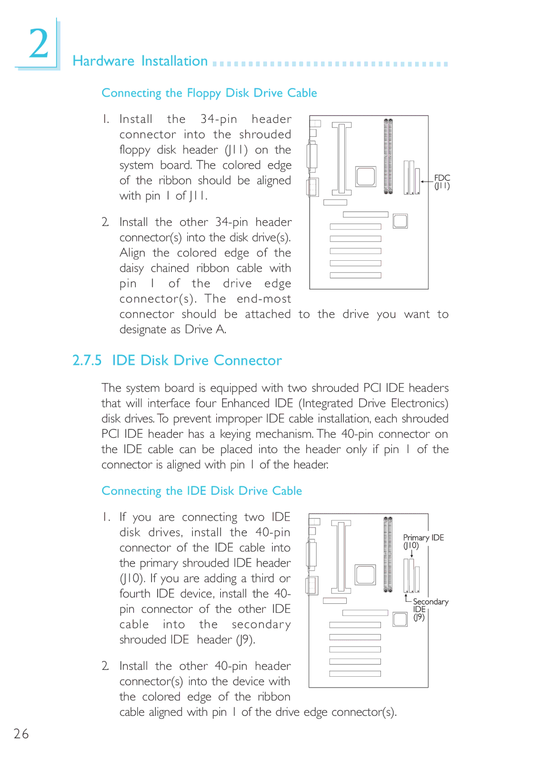
Connecting the Floppy Disk Drive Cable
1. Install the
2. Install the other
connector should be attached to the drive you want to designate as Drive A.
2.7.5 IDE Disk Drive Connector
The system board is equipped with two shrouded PCI IDE headers that will interface four Enhanced IDE (Integrated Drive Electronics) disk drives. To prevent improper IDE cable installation, each shrouded PCI IDE header has a keying mechanism. The
Connecting the IDE Disk Drive Cable
1. If you are connecting two IDE disk drives, install the
2. Install the other
cable aligned with pin 1 of the drive edge connector(s).
26