2
Hardware Installation 


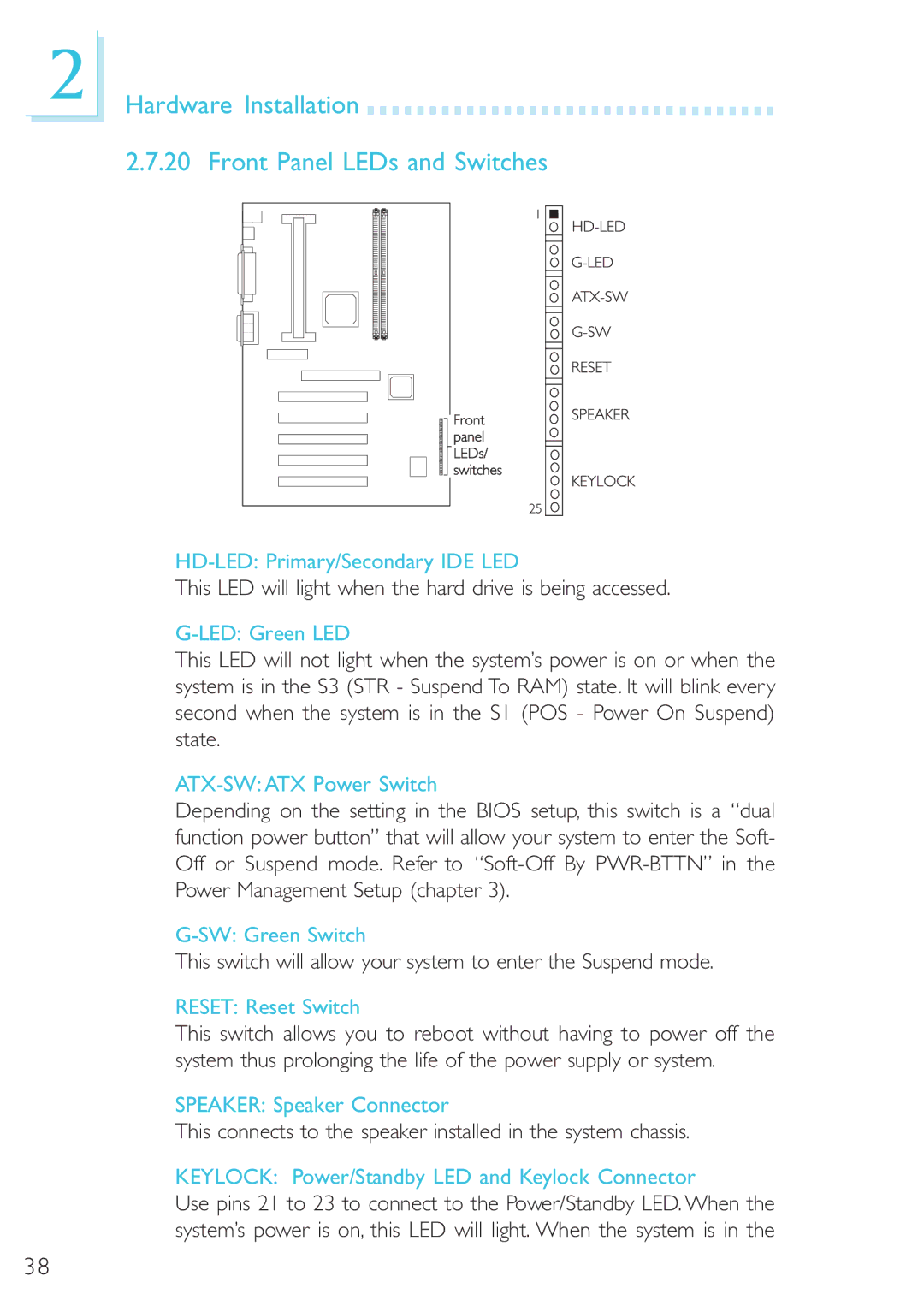
2.7.20 Front Panel LEDs and Switches
This LED will light when the hard drive is being accessed.
G-LED: Green LED
This LED will not light when the system’s power is on or when the system is in the S3 (STR - Suspend To RAM) state. It will blink every second when the system is in the S1 (POS - Power On Suspend) state.
ATX-SW: ATX Power Switch
Depending on the setting in the BIOS setup, this switch is a “dual function power button” that will allow your system to enter the Soft- Off or Suspend mode. Refer to
This switch will allow your system to enter the Suspend mode.
RESET: Reset Switch
This switch allows you to reboot without having to power off the system thus prolonging the life of the power supply or system.
SPEAKER: Speaker Connector
This connects to the speaker installed in the system chassis.
KEYLOCK: Power/Standby LED and Keylock Connector
Use pins 21 to 23 to connect to the Power/Standby LED. When the system’s power is on, this LED will light. When the system is in the
38