Hardware Installation
S1 (POS - Power On Suspend) state, it will blink every second. When the system is in the S3 (STR - Suspend To RAM) state, it will blink every 4 seconds.
Note:
If a system did not
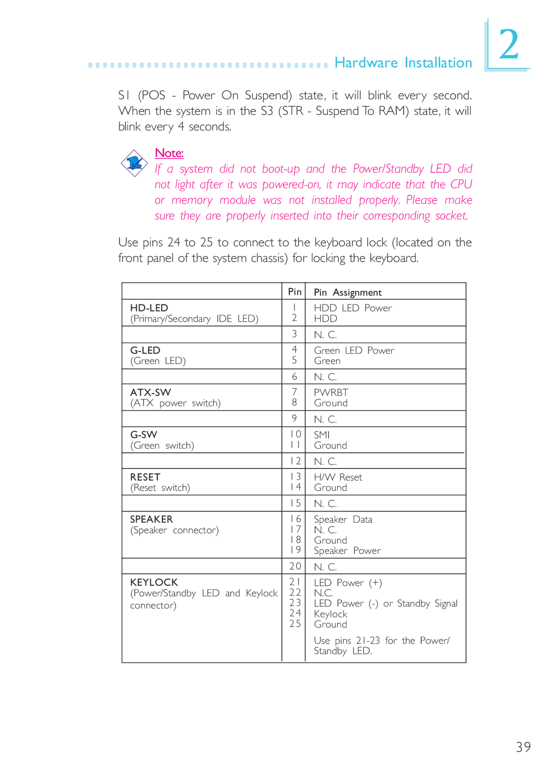
Use pins 24 to 25 to connect to the keyboard lock (located on the front panel of the system chassis) for locking the keyboard.
|
| Pin | Pin Assignment | ||
| 1 | HDD LED Power | |||
(Primary/Secondary IDE LED) | 2 | HDD |
|
| |
|
| 3 | N. C. |
|
|
|
|
|
|
| |
| 4 | Green LED Power | |||
(Green LED) | 5 | Green |
|
| |
|
| 6 | N. C. |
|
|
7 | PWRBT |
|
| ||
(ATX power switch) | 8 | Ground |
|
| |
|
| 9 | N. C. |
|
|
|
|
|
|
|
|
| 1 0 | SMI |
|
| |
(Green | switch) | 1 1 | Ground |
|
|
|
| 1 2 | N. C. |
|
|
RESET |
| 1 3 | H/W Reset | ||
(Reset | switch) | 1 4 | Ground |
|
|
|
| 1 5 | N. C. |
|
|
SPEAKER | 1 6 | Speaker | Data | ||
(Speaker connector) | 1 7 | N. C. |
|
| |
|
| 1 8 | Ground |
|
|
|
| 1 9 | Speaker | Power | |
|
| 2 0 | N. C. |
|
|
KEYLOCK | 2 1 | LED Power (+) | |||
(Power/Standby LED and Keylock | 2 2 | N.C. |
|
| |
connector) | 2 3 | LED Power | |||
|
| 2 4 | Keylock |
|
|
|
| 2 5 | Ground |
|
|
|
|
| Use pins | ||
|
|
| Standby | LED. | |
|
|
|
|
|
|
2
39