950 7.1 specifications
Dolby Laboratories has long been synonymous with cutting-edge audio technology, and the introduction of the Dolby 950 7.1 system is a testament to its commitment to delivering immersive sound experiences. Designed for both professional and home environments, the Dolby 950 7.1 system offers a comprehensive suite of features that elevate audio quality to new heights.At its core, the Dolby 950 7.1 system incorporates a seven-channel setup, which includes left, center, right, left surround, right surround, left back, and right back channels, coupled with a powerful subwoofer for enhanced low-frequency response. This arrangement allows for a truly enveloping soundstage, capable of recreating the nuances of a live performance or the explosive action of a blockbuster film.
One of the standout features of the Dolby 950 7.1 system is its sophisticated audio processing technology. Dolby Digital Plus support ensures that users can experience high-definition audio without compromising on quality. This format allows for increased bit rates and efficient compression, making it ideal for streaming services and Blu-ray content.
Additionally, the system benefits from Dolby Atmos technology, which adds a new dimension of sound by allowing sound designers to place audio elements in three-dimensional space. This innovative approach creates a more natural and realistic listening experience, as sounds can now come from above as well as from the traditional horizontal plane.
Furthermore, the Dolby 950 7.1 is designed with user-friendliness in mind, featuring intuitive setup and calibration options. Advanced room correction technology adjusts audio output based on the unique acoustics of any given space, ensuring optimal performance regardless of environmental factors.
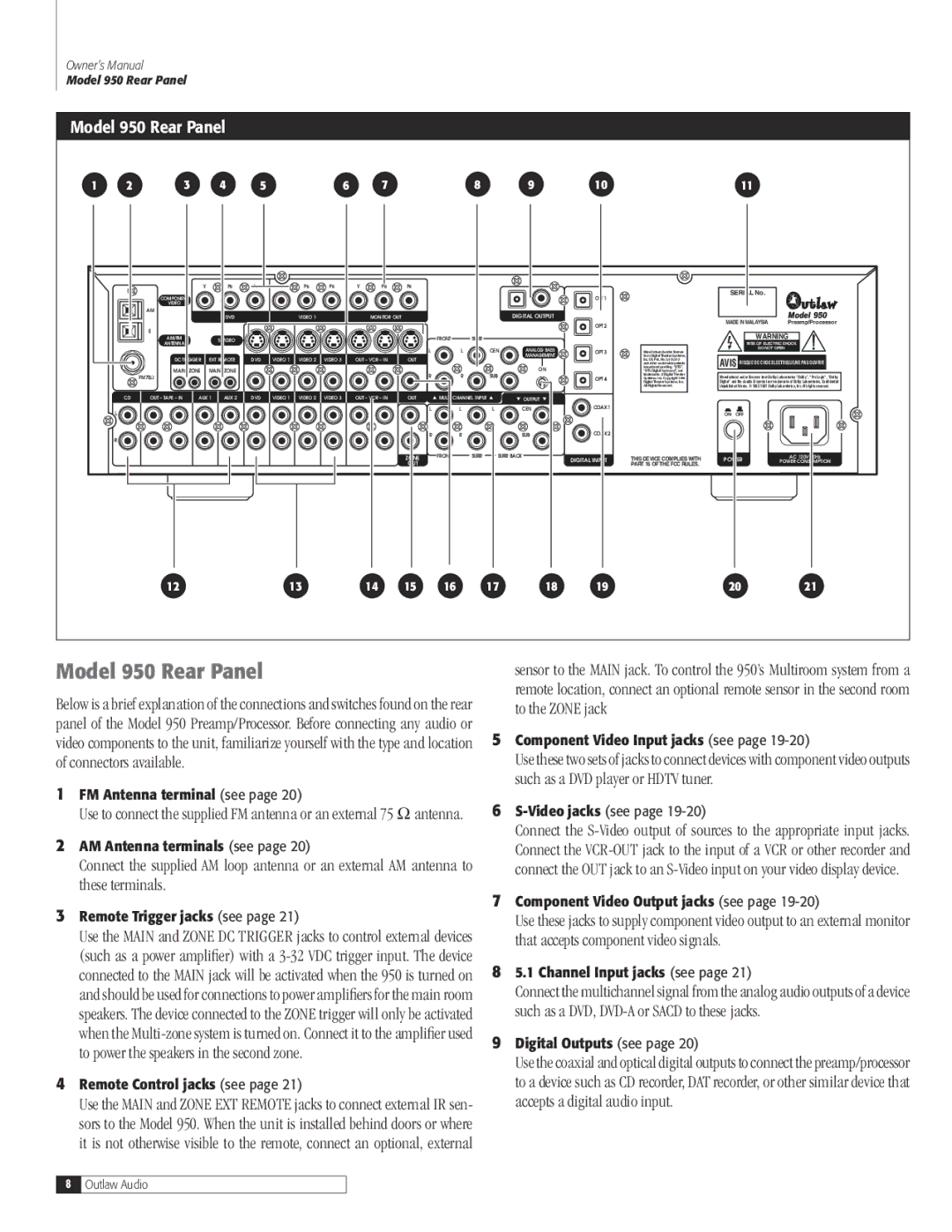
For those looking to integrate this system into a home theater, the Dolby 950 7.1 provides seamless connectivity options. HDMI inputs, optical and coaxial digital inputs, and support for various streaming protocols make it easy to connect to a wide range of devices, from gaming consoles to smart TVs.
In summary, the Dolby 950 7.1 system exemplifies the pinnacle of modern audio technology, boasting features such as seven-channel surround sound, Dolby Digital Plus, and Dolby Atmos capabilities. With its focus on immersive experiences, user-friendly setup, and versatile connectivity, the Dolby 950 7.1 is truly a game-changer for audio enthusiasts and content creators alike. Whether in a professional studio or a personal home theater, this system delivers an unparalleled auditory experience.

