23 electrolux electrical work
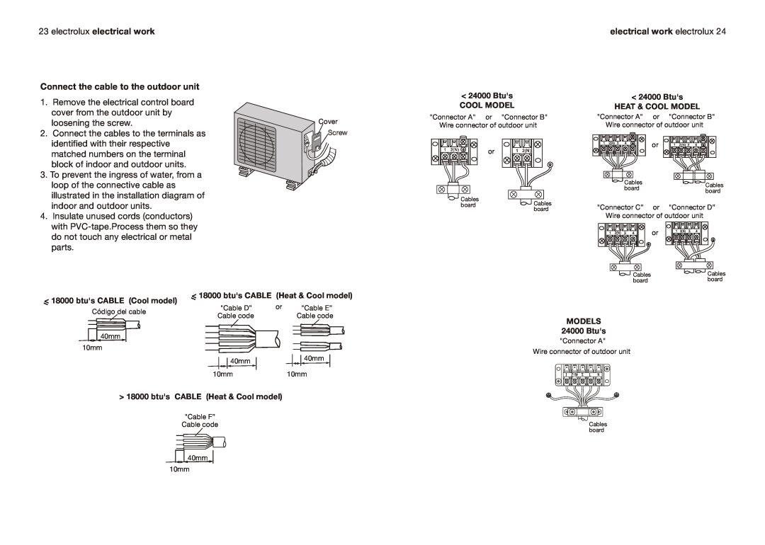
Connect the cable to the outdoor unit
electrical work electrolux 24
1.Remove the electrical control board cover from the outdoor unit by
loosening the screw. | Cover |
2. Connect the cables to the terminals as | Screw |
identified with their respective |
|
matched numbers on the terminal |
|
block of indoor and outdoor units. |
|
3. To prevent the ingress of water, from a |
|
loop of the connective cable as |
|
illustrated in the installation diagram of |
|
indoor and outdoor units. |
|
4.Insulate unused cords (conductors) with
<18000 btu's CABLE (Heat & Cool model)
<18000 btu's CABLE (Cool model)
Código del cable | "Cable D” | or | "Cable E” |
Cable code |
| Cable code | |
|
|
<24000 Btu's
COOL MODEL
"Connector A" or "Connector B" Wire connector of outdoor unit
1 | 2(N) | or | 1 | 2(N) |
|
|
Cables
board![]() Cables board
Cables board
<24000 Btu's
HEAT & COOL MODEL
"Connector A" or "Connector B" Wire connector of outdoor unit
1 | 2(N) | 3 | 4 | or | 1 | 2(N) 3 | 4 |
|
|
|
|
Cables | Cables | |
board | ||
board | ||
| ||
"Connector C” or "Connector D” | ||
Wire connector of outdoor unit |
| |
1 | 2(N) | 3 | 4 | or | 1 | 2(N) | 3 | 4 |
|
|
|
|
Cables | Cables |
board | board |
40mm
10mm
40mm | 40mm |
|
10mm10mm
> 18000 btu's CABLE (Heat & Cool model)
"Cable F”
Cable code
![]() 40mm 10mm
40mm 10mm
MODELS
24000 Btu's
"Connector A"
Wire connector of outdoor unit
Cables board