11 electrolux parts list | indoor unit installation electrolux 12 |
Indoor unit installation
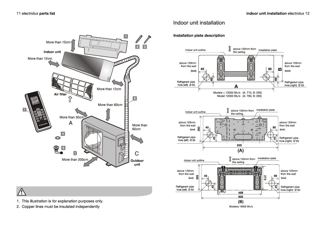
1 | Installation plate description |
|
| |
More than 15cm |
|
|
| |
2 | 3 | above 150mm from |
| |
Indoor unit | Indoor unit outline | Installation plate | ||
the ceiling | ||||
|
|
More than 12cm
above 120mm from the wall
| Refrigerant pipe |
6 | hole (left) Ø 65 |
More than 12cm
Air filter
6
45 |
| 90 | B |
04 |
|
| 04 |
| A |
|
|
Models < 12000 | Btu’s | (A: 710, B: 250) |
|
Model 12000 | Btu’s | (A: 790, B: 265) |
|
above 120mm from the wall
Refrigerant pipe hole (right) Ø 65
More than 60cm
7
More than 30cm
A
4
5
B
| Indoor unit outline | above 150mm from | Installation plate |
| the ceiling |
| |
|
|
| |
More than | above 120mm |
|
|
from the wall |
|
| |
60cm | 293 | 45 | 90 |
| |||
|
|
| |
| Refrigerant pipe | 45 | 45 |
| hole (left) Ø 65 | ||
|
|
| |
|
| 920 |
|
(A)
C
above 120mm from the wall
Refrigerant pipe hole (right) Ø 65
More than 200cm
1.This illustration is for explanation purposes only.
2.Copper lines must be insulated independently
Outdoor | Indoor unit outline | above 150mm from | Installation plate | |
the ceiling |
|
| ||
unit |
|
|
| |
|
|
|
| |
| above 120mm |
|
|
|
| from the wall |
| 272 |
|
| 305 | 45 | 90 | |
|
|
| ||
| Refrigerant pipe | 45 |
| 45 |
| hole (left) Ø 65 | 80 |
|
|
|
|
|
| |
|
| 489 |
|
|
|
| 850 |
|
|
|
| (B) |
|
|
|
| Modelos 18000 Btu’s |
|
|
above 120mm from the wall
Refrigerant pipe hole (right) Ø 65