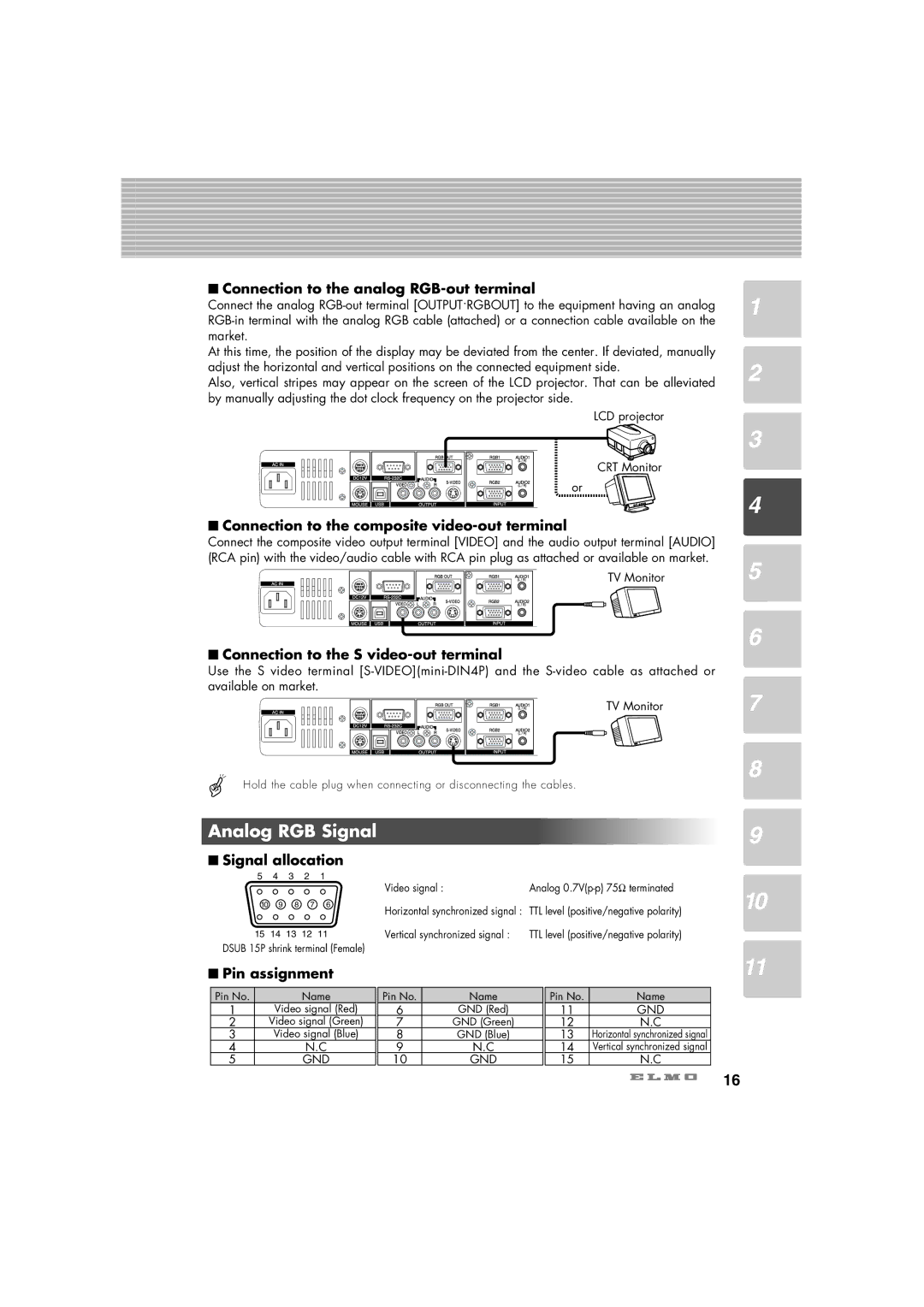
■Connection to the analog RGB-out terminal
Connect the analog
At this time, the position of the display may be deviated from the center. If deviated, manually adjust the horizontal and vertical positions on the connected equipment side.
Also, vertical stripes may appear on the screen of the LCD projector. That can be alleviated by manually adjusting the dot clock frequency on the projector side.
LCD projector
CRT Monitor
or
■Connection to the composite video-out terminal
Connect the composite video output terminal [VIDEO] and the audio output terminal [AUDIO] (RCA pin) with the video/audio cable with RCA pin plug as attached or available on market.
TV Monitor
■Connection to the S video-out terminal
Use the S video terminal
TV Monitor
Hold the cable plug when connecting or disconnecting the cables.
Analog RGB Signal
■Signal allocation
5 | 4 | 3 | 2 | 1 | Video signal : | Analog |
|
|
|
|
| ||
10 | 9 | 8 | 7 | 6 | Horizontal synchronized signal : TTL level (positive/negative polarity) | |
|
|
|
|
| ||
15 14 13 12 11 | Vertical synchronized signal : | TTL level (positive/negative polarity) | ||||
DSUB 15P shrink terminal (Female)
■Pin assignment
Pin No. | Name | Pin No. | Name | Pin No. | Name |
1 | Video signal (Red) | 6 | GND (Red) | 11 | GND |
2 | Video signal (Green) | 7 | GND (Green) | 12 | N.C |
3 | Video signal (Blue) | 8 | GND (Blue) | 13 | Horizontal synchronized signal |
4 | N.C | 9 | N.C | 14 | Vertical synchronized signal |
5 | GND | 10 | GND | 15 | N.C |
1
2
3
4
5
6
7
8
9
10
11
16