Reference Manual
Rosemount 4500
| NOTE |
| Sensor burst pressure limits may be less than clamp pressure limits. |
|
|
|
|
| NOTE |
| Most transmitters are calibrated in the vertical position. Mounting the |
| transmitter in any other position will shift the zero point to the equivalent |
| amount of liquid head caused by the varied mounting position. To reset zero |
| point, refer to “Sensor Trim” on page |
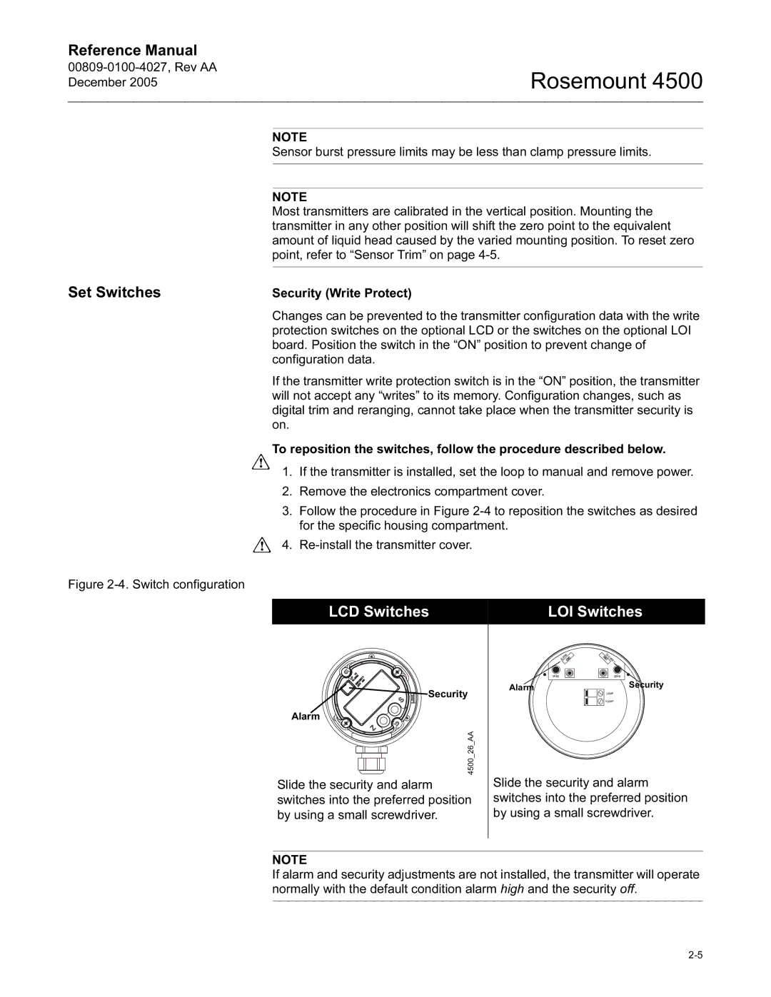
Set Switches |
|
Security (Write Protect) | |
| Changes can be prevented to the transmitter configuration data with the write |
| protection switches on the optional LCD or the switches on the optional LOI |
| board. Position the switch in the “ON” position to prevent change of |
| configuration data. |
| If the transmitter write protection switch is in the “ON” position, the transmitter |
| will not accept any “writes” to its memory. Configuration changes, such as |
| digital trim and reranging, cannot take place when the transmitter security is |
| on. |
| To reposition the switches, follow the procedure described below. |
| 1. If the transmitter is installed, set the loop to manual and remove power. |
| 2. Remove the electronics compartment cover. |
| 3. Follow the procedure in Figure |
| for the specific housing compartment. |
| 4. |
Figure 2-4. Switch configuration
LCD Switches | LOI Switches |
|
|
![]() Security
Security
Alarm
4500_26_AA
Slide the security and alarm switches into the preferred position by using a small screwdriver.
ALARM | SECURITY |
SPAN | ZERO |
AlarmSecurity
+LOOP
Slide the security and alarm switches into the preferred position by using a small screwdriver.
NOTE
If alarm and security adjustments are not installed, the transmitter will operate normally with the default condition alarm high and the security off.