Rosemount 4500
Reference Manual
Grounding | Transmitter Case |
INSTALLING THE LCD METER
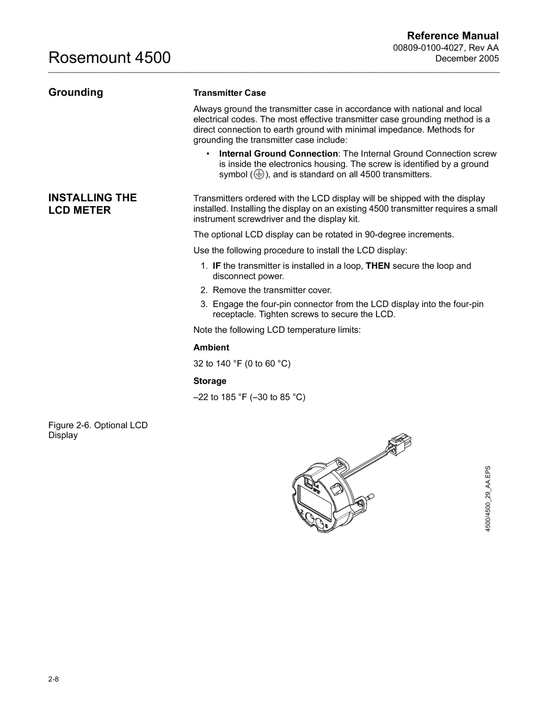
Figure 2-6. Optional LCD Display
Always ground the transmitter case in accordance with national and local electrical codes. The most effective transmitter case grounding method is a direct connection to earth ground with minimal impedance. Methods for grounding the transmitter case include:
•Internal Ground Connection: The Internal Ground Connection screw
is inside the electronics housing. The screw is identified by a ground symbol (  ), and is standard on all 4500 transmitters.
Transmitters ordered with the LCD display will be shipped with the display installed. Installing the display on an existing 4500 transmitter requires a small instrument screwdriver and the display kit.
The optional LCD display can be rotated in 90-degree increments.
Use the following procedure to install the LCD display:
1.IF the transmitter is installed in a loop, THEN secure the loop and disconnect power.
2.Remove the transmitter cover.
3.Engage the four-pin connector from the LCD display into the four-pin receptacle. Tighten screws to secure the LCD.
Note the following LCD temperature limits:
Ambient
32 to 140 °F (0 to 60 °C)
Storage
–22 to 185 °F (–30 to 85 °C)
4500/4500_29_AA.EPS
