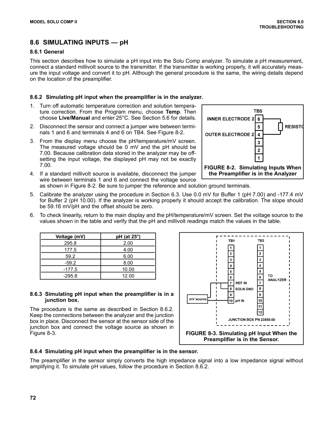
FIGURE 8-2. Simulating Inputs When the Preamplifier is in the Analyzer

MODEL SOLU COMP II

SECTION 8.0


TROUBLESHOOTING

8.6 SIMULATING INPUTS — pH

8.6.1 General

This section describes how to simulate a pH input into the Solu Comp analyzer. To simulate a pH measurement, connect a standard millivolt source to the transmitter. If the transmitter is working properly, it will accurately meas- ure the input voltage and convert it to pH. Although the general procedure is the same, the wiring details depend on the location of the preamplifier.

8.6.2 Simulating pH input when the preamplifier is in the analyzer.

1.Turn off automatic temperature correction and solution tempera- ture correction. From the Program menu, choose Temp. Then choose Live/Manual and enter 25°C. See Section 5.6 for details.

2.Disconnect the sensor and connect a jumper wire between termi- nals 1 and 6 and terminals 4 and 6 on TB4. See Figure 8-2.

3.From the display menu choose the pH/temperature/mV screen. The measured voltage should be 0 mV and the pH should be 7.00. Because calibration data stored in the analyzer may be off- setting the input voltage, the displayed pH may not be exactly

7.00.

4. If a standard millivolt source is available, disconnect the jumper wire between terminals 1 and 6 and connect the voltage source

as shown in Figure 8-2. Be sure to jumper the reference and solution ground terminals.

5.Calibrate the analyzer using the procedure in Section 6.3. Use 0.0 mV for Buffer 1 (pH 7.00) and -177.4 mV for Buffer 2 (pH 10.00). If the analyzer is working properly it should accept the calibration. The slope should be 59.16 mV/pH and the offset should be zero.

6.To check linearity, return to the main display and the pH/temperature/mV screen. Set the voltage source to the values shown in the table and verify that the pH and millivolt readings match the values in the table.


Voltage (mV)

pH (at 25°)


295.8

2.00


177.5

4.00


59.2

6.00


-59.2

8.00


-177.5

10.00


-295.8

12.00


8.6.3Simulating pH input when the preamplifier is in a junction box.

The procedure is the same as described in Section 8.6.2.


Keep the connections between the analyzer and the junction


box in place. Disconnect the sensor at the sensor side of the


junction box and connect the voltage source as shown in


Figure 8-3.

FIGURE 8-3. Simulating pH Input When the


Preamplifier is in the Sensor.

8.6.4 Simulating pH input when the preamplifier is in the sensor.

The preamplifier in the sensor simply converts the high impedance signal into a low impedance signal without amplifying it. To simulate pH values, follow the procedure in Section 8.6.2.

72

Page 81
Image 81
Emerson PN 51-1055pHC/rev.K instruction manual General, Preamplifier is in the Sensor

PN 51-1055pHC/rev.K specifications

The Emerson PN 51-1055pHC/rev.K is a highly advanced and reliable component designed for a wide range of applications in industrial automation and control systems. This device is known for its robust performance, exceptional durability, and integration of cutting-edge technologies, making it an ideal choice for demanding operational environments.

One of the key features of the PN 51-1055pHC/rev.K is its versatility. It is compatible with various systems and can be easily integrated into existing configurations without the need for extensive modifications. This adaptability allows users to streamline their operations and enhance overall efficiency, ensuring that the PN 51-1055pHC/rev.K is suitable for diverse industrial scenarios.

Technologically, the device incorporates advanced sensor capabilities that enable accurate monitoring and measurement of critical parameters. These sensors are designed to provide real-time data, allowing operators to make informed decisions quickly. The real-time diagnostics feature is essential for maintenance, as it helps predict potential issues before they lead to system failures, thereby reducing downtime and operational costs.

The PN 51-1055pHC/rev.K also boasts a rugged construction, built to withstand harsh industrial conditions such as extreme temperatures, vibrations, and moisture. This durability ensures a long lifespan, making it a cost-effective investment for businesses looking to optimize their operations without frequent replacements or repairs.

Another critical characteristic of the Emerson PN 51-1055pHC/rev.K is its user-friendly interface. The device is designed with ease of use in mind, featuring intuitive controls and straightforward setup processes. This accessibility enhances user experience, allowing both seasoned technicians and new operators to utilize its capabilities effectively.

Additionally, the device supports various communication protocols, enabling seamless integration with other equipment and systems. This feature is crucial for creating interconnected environments where data can be shared and analyzed across multiple platforms, fostering smarter and more efficient industrial processes.

In summary, the Emerson PN 51-1055pHC/rev.K stands out for its versatility, advanced sensor technologies, rugged design, user-friendly interface, and communication capabilities. It is a powerful tool for businesses seeking improved automation and control, helping to drive efficiency and enhance operational reliability in any industrial setting.