2
3
4
A
B
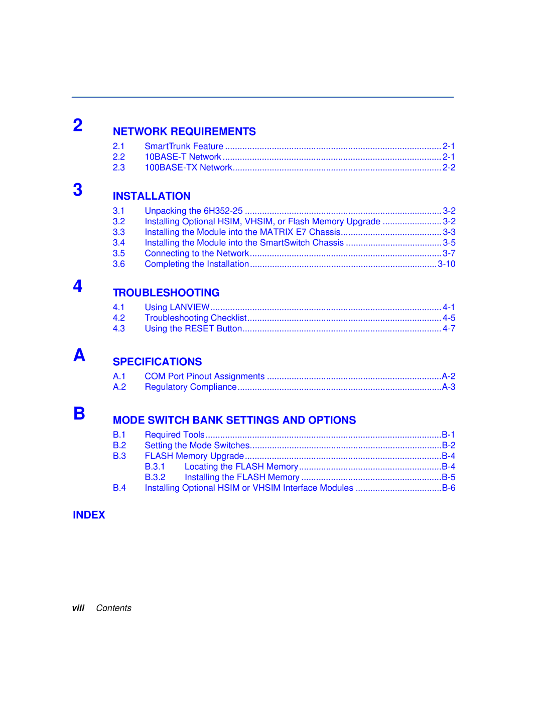
NETWORK REQUIREMENTS
2.1 | SmartTrunk Feature | |
2.2 | ||
2.3 |
INSTALLATION
3.1 | Unpacking the | |
3.2 | Installing Optional HSIM, VHSIM, or Flash Memory Upgrade | |
3.3 | Installing the Module into the MATRIX E7 Chassis | |
3.4 | Installing the Module into the SmartSwitch Chassis | |
3.5 | Connecting to the Network | |
3.6 | Completing the Installation |
TROUBLESHOOTING
4.1 | Using LANVIEW | |
4.2 | Troubleshooting Checklist | |
4.3 | Using the RESET Button |
SPECIFICATIONS
A.1 | COM Port Pinout Assignments | |
A.2 | Regulatory Compliance |
MODE SWITCH BANK SETTINGS AND OPTIONS
B.1 | Required Tools | ||
B.2 | Setting the Mode Switches | ||
B.3 | FLASH Memory Upgrade | ||
| B.3.1 | Locating the FLASH Memory | |
| B.3.2 | Installing the FLASH Memory | |
B.4 | Installing Optional HSIM or VHSIM Interface Modules | ||
