Initial Installation
QUALIFIED INSTALLERS ONLY
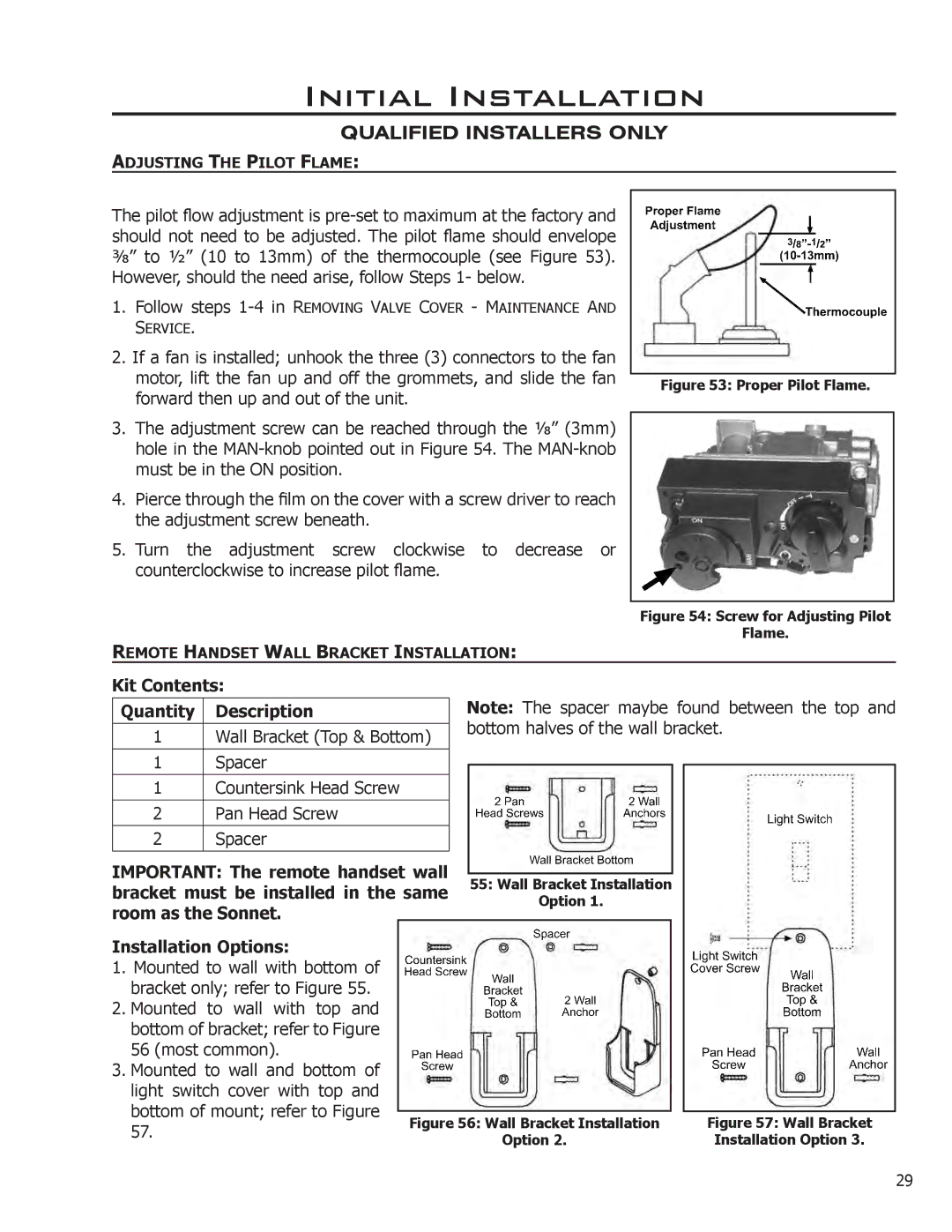
ADJUSTING THE PILOT FLAME:
The pilot flow adjustment is
1.Follow steps
2.If a fan is installed; unhook the three (3) connectors to the fan
motor, lift the fan up and off the grommets, and slide the fan forward then up and out of the unit.
3.The adjustment screw can be reached through the 1⁄8” (3mm) hole in the
4.Pierce through the film on the cover with a screw driver to reach the adjustment screw beneath.
5.Turn the adjustment screw clockwise to decrease or counterclockwise to increase pilot flame.
REMOTE HANDSET WALL BRACKET INSTALLATION:
Figure 53: Proper Pilot Flame.
Figure 54: Screw for Adjusting Pilot
Flame.
Kit Contents:
Quantity | Description |
|
|
1 | Wall Bracket (Top & Bottom) |
|
|
1 | Spacer |
|
|
1 | Countersink Head Screw |
|
|
2 | Pan Head Screw |
2Spacer
IMPORTANT: The remote handset wall bracket must be installed in the same room as the Sonnet.
Note: The spacer maybe found between the top and bottom halves of the wall bracket.
55:Wall Bracket Installation Option 1.
Installation Options:
1.Mounted to wall with bottom of bracket only; refer to Figure 55.
2.Mounted to wall with top and bottom of bracket; refer to Figure 56 (most common).
3.Mounted to wall and bottom of light switch cover with top and bottom of mount; refer to Figure 57.
| Figure 57: Wall Bracket |
Figure 56: Wall Bracket Installation | |
Option 2. | Installation Option 3. |
29