|
| Initial Installation | ||
|
|
| QUALIFIED INSTALLERS ONLY | |
|
|
| Table 5: Vent termination clearances | |
|
|
|
|
|
| Minimum Clearance |
| Description |
|
|
|
|
|
|
| 3 ft (0.9 m) |
| Clearance above the highest point where it passes through a roof surface, |
|
|
| refer to Figure 39. |
| |
|
|
|
| |
|
|
|
|
|
| 24 in (0.6 m) |
| Clearance above a roof ridge, any other portion of a building, or any other |
|
|
| obstruction within a horizontal distance of 10 feet (3 m), refer to Figure 39. |
| |
|
|
|
| |
| 5 ft (1.5 m) |
| Clearance for a vent or chimney above either the highest connected appli- |
|
|
| ance drafthood outlet, or flue collar. |
| |
|
|
|
| |
|
|
|
|
|
| 6 ft (1.83 m) |
| Clearance to mechanical air supply inlet. |
|
| 3ft (0.9m) |
| Clearance to each side of center line extended above meter/regulator as- |
|
|
| sembly. |
| |
|
|
|
| |
|
|
|
|
|
| 6 ft (1.83 m) |
| Radial clearance around service regulator vent outlet. |
|
|
|
|
|
|
| 12 in (30 cm) |
| Clearance above grade, verandah, porch, deck, or balcony. |
|
|
|
|
|
|
|
|
| Clearance to a building opening or combustion air inlet of another appli- |
|
| 3 ft (0.9 m) |
| ance, except with the approval of the authority having jurisdiction for the |
|
|
|
| following reduced clearances. |
|
|
|
|
|
|
| 9 in (0.23 m) |
| Exception for inputs up to and including 50,000 Btu/h (15kW) |
|
|
|
|
|
|
| 12 in (0.3 m) |
| Exception for inputs exceeding 50,000 Btu/h (15kW) but not exceeding |
|
|
| 100,000 Btu/h (30kW) |
| |
|
|
|
| |
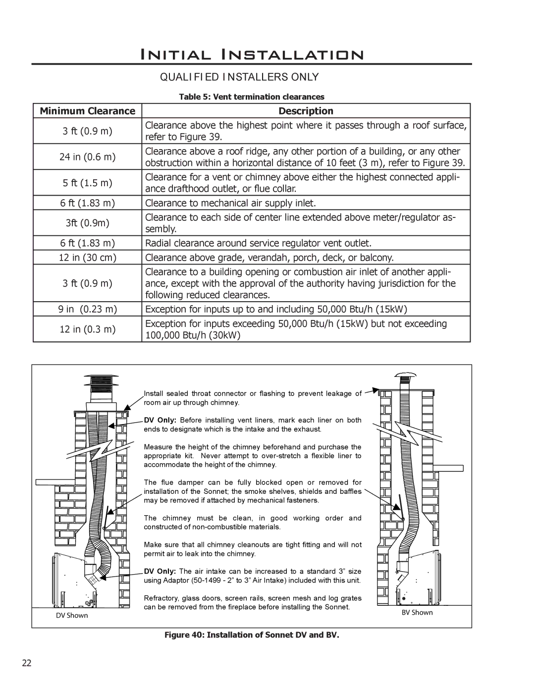
Install sealed throat connector or flashing to prevent leakage of ![]()
![]()
![]()
![]()
![]()
![]()
![]()
room air up through chimney.
DV Only: Before installing vent liners, mark each liner on both ends to designate which is the intake and the exhaust.
Measure the height of the chimney beforehand and purchase the appropriate kit. Never attempt to
The flue damper can be fully blocked open or removed for
installation of the Sonnet; the smoke shelves, shields and baffles
![]() may be removed if attached by mechanical fasteners.
may be removed if attached by mechanical fasteners.
The chimney must be clean, in good working order and constructed of
Make sure that all chimney cleanouts are tight fitting and will not permit air to leak into the chimney.
DV Only: The air intake can be increased to a standard 3” size
![]()
![]()
![]()
![]()
![]()
![]()
![]()
![]()
![]()
![]() using Adaptor
using Adaptor
Refractory, glass doors, screen rails, screen mesh and log grates can be removed from the fireplace before installing the Sonnet.
�� �����
�� ����� |
Figure 40: Installation of Sonnet DV and BV.
22