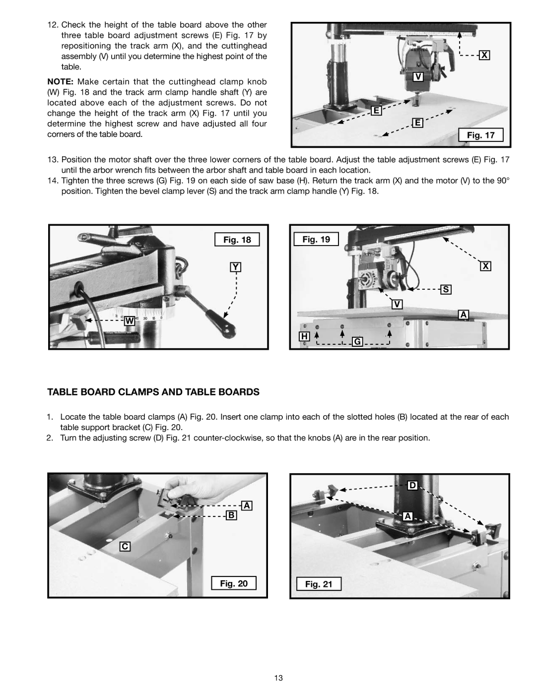
12.Check the height of the table board above the other three table board adjustment screws (E) Fig. 17 by repositioning the track arm (X), and the cuttinghead assembly (V) until you determine the highest point of the table.
NOTE: Make certain that the cuttinghead clamp knob
(W)Fig. 18 and the track arm clamp handle shaft (Y) are located above each of the adjustment screws. Do not change the height of the track arm (X) Fig. 17 until you determine the highest screw and have adjusted all four corners of the table board.
![]()
![]() X
X
V
E
E
Fig. 17
13.Position the motor shaft over the three lower corners of the table board. Adjust the table adjustment screws (E) Fig. 17 until the arbor wrench fits between the arbor shaft and table board in each location.
14.Tighten the three screws (G) Fig. 19 on each side of saw base (H). Return the track arm (X) and the motor (V) to the 90° position. Tighten the bevel clamp lever (S) and the track arm clamp handle (Y) Fig. 18.
![]()
![]() W
W
Fig. 18
Y
Fig. 19
H ![]()
![]()
X
![]()
![]() S
S
V
A
G
TABLE BOARD CLAMPS AND TABLE BOARDS
1.Locate the table board clamps (A) Fig. 20. Insert one clamp into each of the slotted holes (B) located at the rear of each table support bracket (C) Fig. 20.
2.Turn the adjusting screw (D) Fig. 21
![]() A
A
![]()
![]() B
B
C
Fig. 20
D |
A |
Fig. 21 |
13