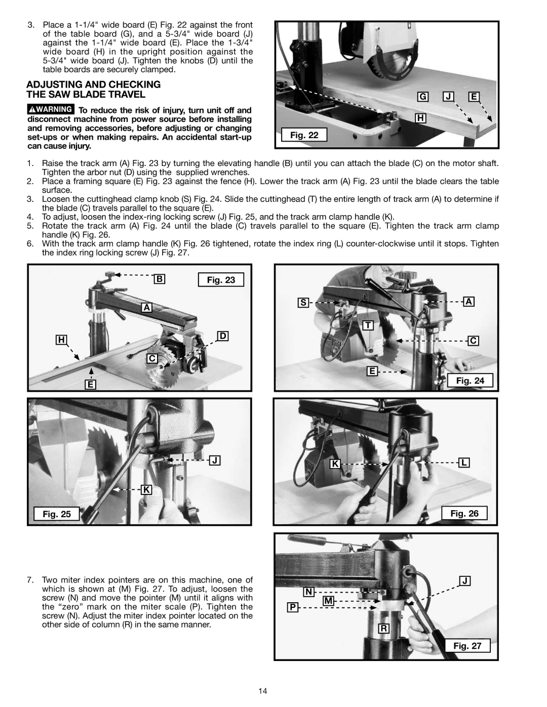
3.Place a
ADJUSTING AND CHECKING
THE SAW BLADE TRAVEL
![]() To reduce the risk of injury, turn unit off and disconnect machine from power source before installing and removing accessories, before adjusting or changing
To reduce the risk of injury, turn unit off and disconnect machine from power source before installing and removing accessories, before adjusting or changing
Fig. 22
G
H
J
E
1.Raise the track arm (A) Fig. 23 by turning the elevating handle (B) until you can attach the blade (C) on the motor shaft. Tighten the arbor nut (D) using the supplied wrenches.
2.Place a framing square (E) Fig. 23 against the fence (H). Lower the track arm (A) Fig. 23 until the blade clears the table surface.
3.Loosen the cuttinghead clamp knob (S) Fig. 24. Slide the cuttinghead (T) the entire length of track arm (A) to determine if the blade (C) travels parallel to the square (E).
4.To adjust, loosen the
5.Rotate the track arm (A) Fig. 24 until the blade (C) travels parallel to the square (E). Tighten the track arm clamp handle (K) Fig. 26.
6.With the track arm clamp handle (K) Fig. 26 tightened, rotate the index ring (L)
|
|
|
| Fig. 23 |
|
| b | ||
|
|
|
|
|
|
|
|
|
|
a |
|
s | a |
h | d |
| |
| c |
| e |
t
e ![]()
![]()
c
Fig. 24
![]()
![]() j
j
![]()
![]() k
k
Fig. 25
7.Two miter index pointers are on this machine, one of which is shown at (M) Fig. 27. To adjust, loosen the screw (N) and move the pointer (M) until it aligns with the “zero” mark on the miter scale (P). Tighten the screw (N). Adjust the miter index pointer located on the other side of column (R) in the same manner.
k | l |
Fig. 26
| j |
| n |
p | m |
| |
| r |
| Fig. 27 |
14
